Vehicle-installation direction detection apparatus enabling accurate detection of target body directions irrespective of vehicle speed

a detection apparatus and vehicle technology, applied in the direction of multi-channel direction-finding systems using radio waves, instruments, measurement devices, etc., can solve the problems of inability of the apparatus to distinguish the respective directions of a plurality of target bodies, low direction detection resolution, and extremely limited space available for installing systems, etc., to achieve accurate detection, eliminate correlation, and improve detection resolution

Active Publication Date: 2009-05-14
DENSO CORP
View PDF16 Cites 17 Cited by
  • Summary
  • Abstract
  • Description
  • Claims
  • Application Information

AI Technical Summary

Benefits of technology

[0015]It is an objective of the present invention to overcome the above problem, by providing a direction detection apparatus for installation on a vehicle, whereby respective directions of target bodies can be reliably detected, and in particular whereby the number of target bodies whose directions can be separately detected concurrently is not reduced when the vehicle on which the apparatus is installed is travelling at a low speed, or is halted.
[0023]As a result, reliable direction detection can be achieved, irrespective of the travel speed of the vehicle on which the apparatus is installed, and without a reduction (due to the vehicle being halted or moving at a low speed) in the number of target bodies whose directions can be separately distinguished by the apparatus.
[0024]According to a second aspect, the invention provides a direction detection apparatus which can achieve a high accuracy of direction detection even when the local vehicle is travelling at a low speed or is halted. With such an apparatus, if the vehicle speed does not exceed the threshold value, so that direction detection by the aforementioned first direction detection means is not selected, then the second direction detection means detects an approximate direction of the target bodies. A third direction detection means then defines a plurality of additional directions, centered on the approximate direction. A quasi-observed matrix is also generated, which is a correlation matrix expressing the correlation relationships between respective presumptive received signals that would be obtained from the antenna elements if reflected waves were to be received by the array antenna after arriving along the additional directions.
[0027]Hence, the additional observed matrix can be used with an appropriate direction detection method such as the MUSIC algorithm to reliably detect the respective directions of one or more target bodies from which radar waves are reflected, even if the target bodies are stationary and are close together and located at close range.
[0029]Hence from this aspect of the invention, if the velocity of the local vehicle does not exceed the threshold value, direction detection is performed by the third direction detection means using the same estimation algorithm as is used by the first direction detection means, so that accurate detection can be achieved.
[0030]According to a third aspect, the invention provides a direction detection apparatus having approximate direction detection means for approximately detecting the direction(s) of one or more target bodies by utilizing DBF (digital beam forming), based on the main lobe of a signal reception pattern of an array antenna. An observed matrix expressing a correlation relationship between the actual received signals from the antenna elements of the array antenna is then generated. In addition, a quasi-observed matrix expressing correlation between a plurality of additional directions as described above is derived, and added to the observed matrix to obtain an additional observed matrix in which the effects of correlation are eliminated. The additional observed matrix is then used in executing a direction detection algorithm capable of a higher detection resolution than the approximate direction detection resolution, such as the MUSIC algorithm. Hence, direction detection can be accurately achieved to a high degree of resolution, irrespective of the velocity of the local vehicle and target objects, by using only a single processing sequence.

Problems solved by technology

In the case of a radar apparatus that is be installed on a vehicle (referred to in the following as the “local vehicle” for brevity of description) for detecting objects such as other vehicles in the environment, the space available for installing the system is extremely limited.
With such a method, the problem arises that since the beam width of the array antenna is large, the direction detection resolution is low.
Hence it may be impossible for the apparatus to distinguish the respective directions of a plurality of target bodies when the target objects are close together.
However when the difference between the velocities of the target objects is very low or zero, e.g., as occurs when the local vehicle and target objects are halted, it becomes difficult for the apparatus to accurately detect the directions of the target bodies (as illustrated in diagram (b) of FIG. 5).
Hence the respective directions of target bodies cannot be accurately detected by using an algorithm such as MUSIC.
If spatial averaging of respective correlation matrixes obtained from a plurality of successively shifted antenna sub-arrays is utilized as described above, then the problem arises that the number of target bodies whose directions can be separately detected will be reduced.
In particular, if the radar apparatus is to be made compact in size, so that the array antenna must be small, then this becomes a serious problem.

Method used


Image

  • Vehicle-installation direction detection apparatus enabling accurate detection of target body directions irrespective of vehicle speed
  • Vehicle-installation direction detection apparatus enabling accurate detection of target body directions irrespective of vehicle speed
  • Vehicle-installation direction detection apparatus enabling accurate detection of target body directions irrespective of vehicle speed

Examples


Embodiment Construction

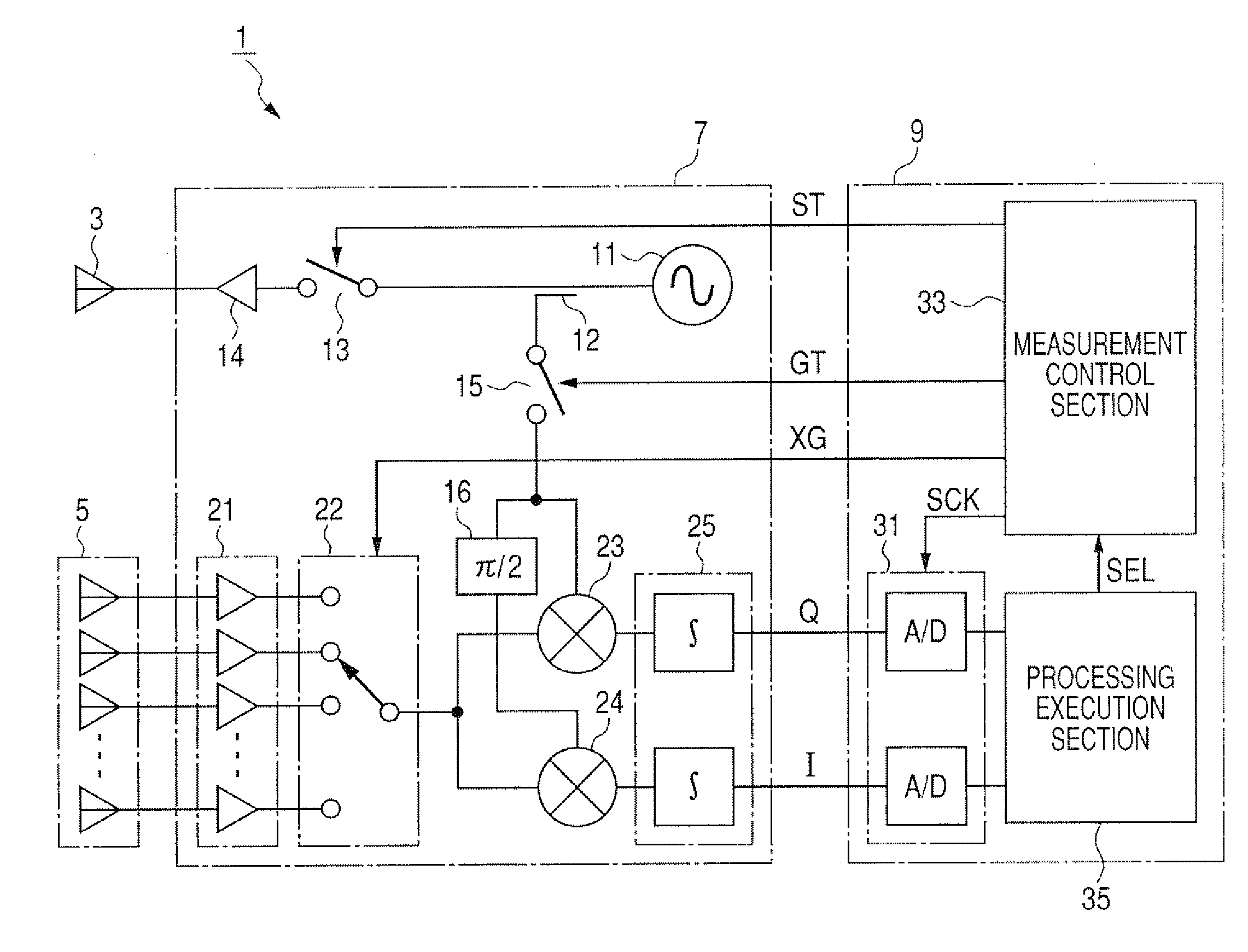
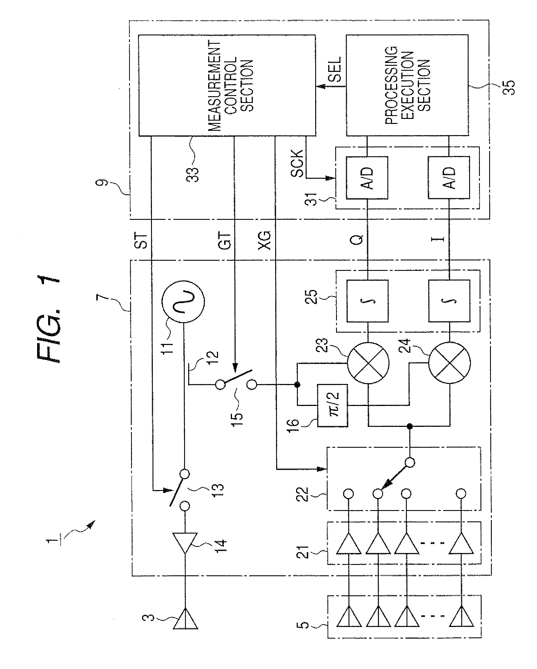
[0037]FIG. 1 is a block diagram of a pulse radar apparatus 1 which is installed on a local vehicle, and which detects respective directions of other vehicles, pedestrians, obstacles, etc., in the environment. As shown in FIG. 1, the pulse radar apparatus 1 includes a transmitting antenna 3, a receiving antenna 5, a RF amplifier circuit section 7, and a signal processing section 9. The transmitting antenna 3 transmits radar waves, and the receiving antenna 5 receives radar waves that have been reflected from a target body after being transmitted from the transmitting antenna 3. The RF amplifier circuit section 7 generates a transmission signal as a series of high-frequency pulses, which are supplied to the transmitting antenna 3, and also processes received signals that are supplied from the receiving antenna 5. The signal processing section 9 controls the operation of the RF amplifier circuit section 7, and detects information (referred to in the following as target body information...


PUM


Abstract

A vehicle-installed direction detection apparatus is controlled in accordance with the vehicle speed, to detect respective directions of one or more target objects by selectively applying high-resolution detection processing or low-resolution detection processing to received signals obtained from the elements of an array antenna of a radar apparatus, with the selection being determined in accordance with whether the speed attains a predetermined threshold value. The high-resolution detection processing is based on correlation between the received signals, utilizing an null scan type of algorithm such as MUSIC, while the low-resolution detection processing is based for example on digital beam forming.

Description

CROSS-REFERENCE TO RELATED APPLICATIONS[0001]This application is based on and incorporates herein by reference Japanese Patent Application No. 2007-292156 filed on Nov. 9, 2007.BACKGROUND OF THE INVENTION[0002]1. Field of Application[0003]The present invention relates to a direction detection apparatus which estimates the direction of arrival of electromagnetic waves, based on signals received by an array antenna.[0004]In particular, the invention relates to a direction detection apparatus implemented as a radar apparatus installed on a vehicle, which transmits radar waves and detects the directions of target bodies based on respective directions of arrival of reflected waves from the target bodies.[0005]2. Description of Related Art[0006]Types of radar apparatus which perform direction detection are known, having an array antenna for receiving radar waves, with the array antenna formed of a plurality of antenna elements. Radar waves transmitted from the apparatus are reflected from...

Claims


Application Information

Patent Timeline
Patent Type & Authority Applications(United States)
IPC IPC(8): G01S13/00G01S13/58
CPCG01S3/74G01S13/34G01S2013/9353G01S13/931G01S13/42G01S2013/932
Inventor MIYAKE, YASUYUKI
Owner DENSO CORP
Why Eureka
Try Eureka