Radar apparatus enabling simplified suppression of interference signal components which result from reception of directly transmitted radar waves from another radar apparatus

a radar and interference signal technology, applied in the direction of reradiation, measurement devices, instruments, etc., can solve the problems of inability to obtain accurate phase information, inability to estimate the direction of the target object, complex apparatus,

Active Publication Date: 2009-05-14
DENSO CORP
View PDF40 Cites 83 Cited by
  • Summary
  • Abstract
  • Description
  • Claims
  • Application Information

AI Technical Summary

Benefits of technology

[0022]It is an objective of the present invention to overcome the above problems, by providing a FM-CW or FM type of electronic scanni...

Problems solved by technology

However this makes it necessary to utilize separate A/D converters for each of the channels, so that the apparatus becomes complex and expensive.
However in practice, from reasons of cost, etc., it is generally necessary to use circuitry for the channels selector switch 7 that is only capable of relatively low-speed antenna signal switching, so that the channel selector switch 7 can only be operated at a relatively low drive frequency.
However another problem exists, which will be described referring first to FIG. 2.
Thus, accurate phase information cannot be obtained for the desired received signal components (resulting from the reflected radar waves Rx1), so that the direction of the target object cannot be estimated.
However with a time-division multiplexing type of radar apparatus, it may not be possible to accurately determine the arrival direction of the interference waves.
In such a case, it may not be possible to use phase relationships between channel signals for detecting the direction of an interference source, for the purpose of suppressing an interference signal transmitted from that source, or to perform phase compensation for time delays between the signals of respective channels.
This p...

Method used


Image

  • Radar apparatus enabling simplified suppression of interference signal components which result from reception of directly transmitted radar waves from another radar apparatus
  • Radar apparatus enabling simplified suppression of interference signal components which result from reception of directly transmitted radar waves from another radar apparatus
  • Radar apparatus enabling simplified suppression of interference signal components which result from reception of directly transmitted radar waves from another radar apparatus

Examples


Embodiment Construction

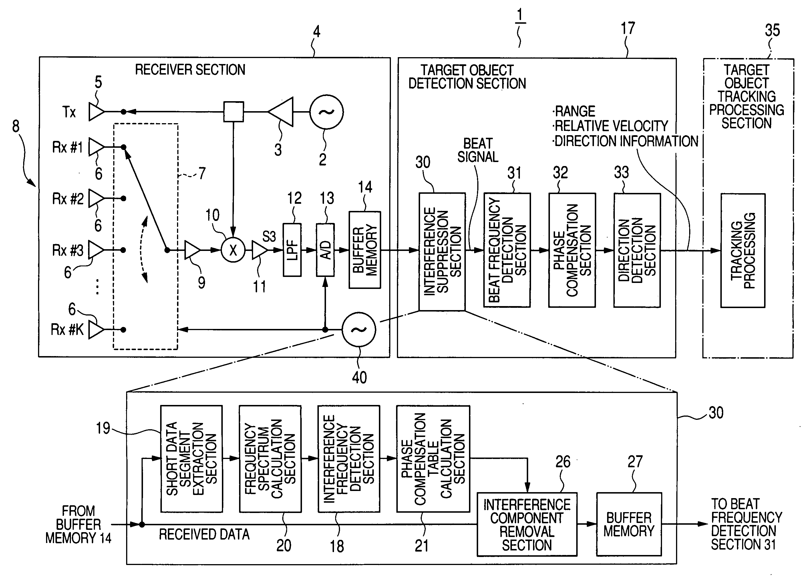
[0048]FIG. 5 is a block diagram showing the overall configuration of an embodiment of an electronic scanning radar apparatus, denoted by numeral 1. This is a FM-CW type of radar apparatus, which utilizes modulation of continuous electromagnetic waves (CW) by a transmission signal Tx, using frequency modulation (FM). The electronic scanning radar apparatus 1 is installed on a vehicle, and serves to detect the distance and relative velocity of a target object that is travelling ahead of the vehicle, and the direction to that target object. The detection results obtained by the electronic scanning radar apparatus 1 are used as information for controlling the running of the vehicle, etc. The transmitted waves are in the microwave frequency range.

[0049]As shown, the electronic scanning radar apparatus 1 includes a receiver section 4, a target object detection section 17, and a target object tracking processing section 35. The target object detection section 17 includes a interference sup...


PUM


Abstract

In a FM-CW or CW radar apparatus, when interference components are Contained in channel signals obtained as beat signals from array antenna elements of respective channels, and the interference components result from directly receiving transmitted CW radar waves from an external source, phase shifting is applied to each of the channel signals to shift respective phases of the interference components of the respective channels to a condition corresponding to reception of interference waves from a predetermined direction. The interference components are then eliminated, and reverse phase shifting is applied to restore remaining components of the channel signals to their original phase condition.

Description

CROSS-REFERENCE TO RELATED APPLICATIONS[0001]This application is based on and incorporates herein by reference Japanese Patent Application No. 2007-292856 filed on Nov. 12, 2007.BACKGROUND OF THE INVENTION[0002]1. Field of Application[0003]The present invention relates to an electronic scanning type of radar apparatus, and in particular to a vehicle-installation FM-CW (frequency modulation, continuous wave) or CW (continuous wave) type of electronic scanning radar apparatus which enables an interference component contained in a received signal to be suppressed.[0004]2. Description of Related Art[0005]Types of radar apparatus for vehicle installation are known which can detect the distance, velocity and direction (i.e., azimuth bearing) of a target object such as a preceding vehicle, for use in collision avoidance and vehicle control. A vehicle equipped with such a radar apparatus, and for which the apparatus operation is being described, will be referred to in the following as the l...

Claims


Application Information

Patent Timeline
IPC IPC(8): G01S13/93G01S13/931
CPCG01S7/023G01S13/931G01S13/345G01S7/2813
Inventor SHIRAI, HIDEKIYAMANO, CHIHARUNATSUME, KAZUMAWATANABE, YUUSAKAMOTO, MAI
Owner DENSO CORP
Why Eureka
Try Eureka