
Keypad Panel Assembly Having Laterally-Illuminated Keypad Surface

a keypad and assembly technology, applied in the field of keypad panels, can solve the problems of increasing the number of manufacturing processes, increasing the work hours of users operating the keypads on the electronic device, and increasing the cost, so as to improve the backlight effect and see the location of each keypad more clearly

Inactive Publication Date: 2009-05-14
ICHIA TECH
View PDF6 Cites 14 Cited by
  • Summary
  • Abstract
  • Description
  • Claims
  • Application Information

AI Technical Summary

Benefits of technology

"The present invention provides a keypad panel assembly with a backlight effect that is easy to manufacture and improves the user's ability to see the keypad location. The assembly includes a light-guiding plate and a panel with protruding strips and light-guiding particles. The panel has rectangular keypads with icons and hollowed portions between the keypads and the panel. The protruding strips pass through the hollowed portions, and the height of the protruding strip is larger than the keypad and icon. The technical effects of the invention include improved backlight effect and easy manufacturing of the keypad panel assembly."

Problems solved by technology

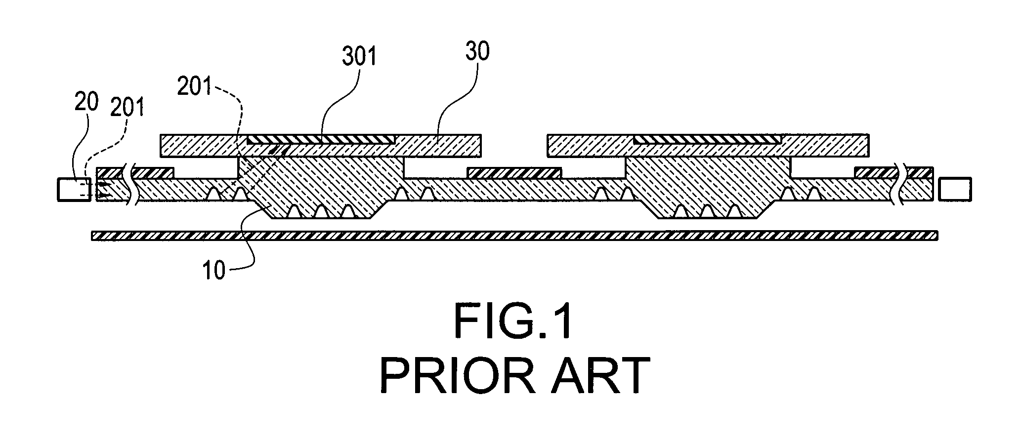
However, in a dark or insufficiently-illuminated environment, it is difficult for the user to operate the keypads on the electronic device.
As a result, the working hours and number of processes for manufacturing the keypads will be increased, which also increases the cost.

Method used


Image

  • Keypad Panel Assembly Having Laterally-Illuminated Keypad Surface
  • Keypad Panel Assembly Having Laterally-Illuminated Keypad Surface
  • Keypad Panel Assembly Having Laterally-Illuminated Keypad Surface

Examples


Embodiment Construction

[0021]The detailed description and the technical contents of the present invention will be explained with reference to the accompanying drawings.

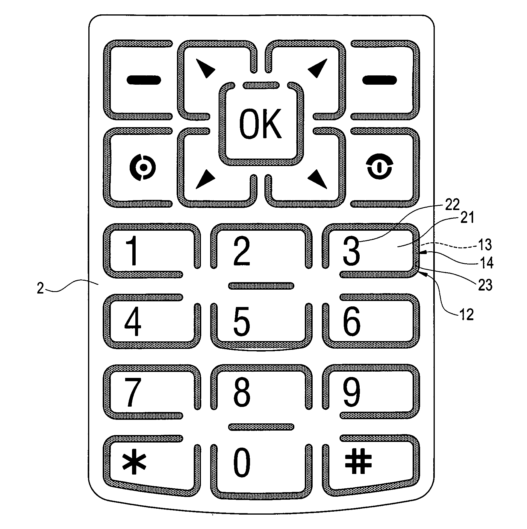
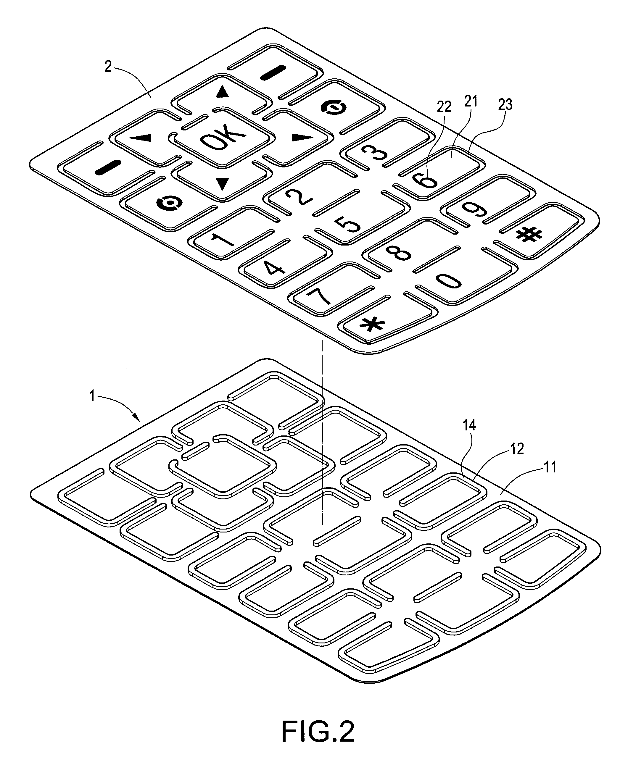
[0022]FIGS. 2 to 4 are an exploded view, an elevation view and a side cross-sectional view showing the keypad panel assembly of the present invention respectively. As shown in these figures, the present invention provides a keypad panel assembly having a laterally-illuminated keypad surface, which includes a light-guiding plate 1 and a panel 2.

[0023]The light-guiding plate 1 is made of either plastic material or rubber material. The light-guiding plate 1 has a carrier 11 thereon. The front surface of the carrier 11 is provided thereon with a plurality of protruding strips 12. Each protruding strip 12 encloses a rectangular shape, so that each protruding strip is provided with a plurality of light-guiding particles 13 at positions corresponding to a back surface of the carrier 11. The light-guiding particles 13 can be provided in the interio...


PUM


Abstract

A keypad panel assembly having a laterally-illuminated keypad surface is arranged on an electronic device. The keypad panel includes a light-guiding plate and a panel. The light-guiding plate has a carrier thereon. One side surface of the carrier is provided with a plurality of protruding strips. Each protruding strip is provided with a plurality of light-guiding particles at positions corresponding to the other side surface of the carrier. The top surface of the protruding strip is provided with a reflective layer. The panel is arranged on one side surface of the carrier, and is provided thereon with a plurality of rectangular keypads. One side surface of each keypad is provided with an icon, and a plurality of hollowed portions is provided between each keypad and the panel. Each hollowed portion encloses a rectangular shape and corresponds to the protruding strip of the carrier. After the protruding strip passes through the hollowed portion, the height of the protruding strip is larger than those of the keypad and the icon. After the light generated by a backlight source of the electronic device is introduced from one side of the light-guiding plate, the light-guiding particles focus the light on the protruding strip. Then, the light illuminates the keypad surface from both sides of the protruding strip, so that a user can see the icon displayed on the keypad surface clearly.

Description

BACKGROUND OF THE INVENTION[0001]1. Field of the Invention[0002]The present invention relates to a keypad panel, and in particular to a keypad panel assembly having a laterally-illuminated keypad surface.[0003]2. Description of Prior Art[0004]Keypad assembly is one of the primary input means for an electronic device. The surface of each keypad of the keypad assembly is provided with corresponding numerals, characters, phonetic symbols, roots for an input method and various functional icons, so that a user can input data or perform various functions of the electronic device. Therefore, for an electronic device, the keypad assembly is a very important input means.[0005]When the electronic device is operated in an environment having sufficient illumination, the user can see the location of each keypad very clearly, so that the user will not press the wrong keypad in operation. However, in a dark or insufficiently-illuminated environment, it is difficult for the user to operate the keyp...

Claims


Application Information

Patent Timeline
Patent Type & Authority Applications(United States)
IPC IPC(8): G06F3/02
CPCG06F3/0202H01H13/83H01H2209/07H01H2219/0622H01H2219/06H01H2219/062H01H2209/082
Inventor HUANG, CHING-CHIH
Owner ICHIA TECH
Learn More