Display apparatus, driving method for display apparatus and electronic apparatus

a technology of display apparatus and driving method, applied in the field of display, can solve the problems of deterioration of screen image uniformity, difference in luminance, damage to screen image uniformity, etc., and achieve the effect of improving screen image uniformity, reducing the difference in operation condition, and improving the uniformity of screen imag

Inactive Publication Date: 2009-05-14
JOLED INC
View PDF4 Cites 41 Cited by
  • Summary
  • Abstract
  • Description
  • Claims
  • Application Information

AI Technical Summary

Benefits of technology

[0023]In the display apparatus, the scanning direction of the line-sequential driving is controlled so as to be reversed between each adjacent ones of the blocks. Consequently, the difference in operation condition is minimized between pixel rows positioned on the boundary between adjacent blocks, and no difference in luminance appears on the boundary. Therefore, the uniformity of the screen image of the display apparatus can be improved. The last pixel row of a preceding one of a pair of preceding and succeeding blocks is line-sequentially scanned last in the block whereas also the first pixel row in the succeeding block is line-sequentially scanned last in the block. This is because the scanning direction of the line-sequential driving is controlled so as to be reversed between adjacent blocks. Both of the last pixel row of the preceding block and the top pixel row of the succeeding block which are adjacent each other are line-sequentially scanned last in the individual blocks and are driven in the same driving condition in time. Consequently, no difference in luminance appears between the two pixel rows, and the uniformity of the screen image can be improved.

Problems solved by technology

Existing block driving has a problem in that, between pixel rows positioned on the boundary between adjacent blocks, a difference in luminance is caused by a difference in operation condition and damages the uniformity of the screen image.
This appears as a delicate difference in luminance between the two pixel rows and makes a cause of deterioration of the uniformity of the screen image.

Method used


Image

  • Display apparatus, driving method for display apparatus and electronic apparatus
  • Display apparatus, driving method for display apparatus and electronic apparatus
  • Display apparatus, driving method for display apparatus and electronic apparatus

Examples


Embodiment Construction

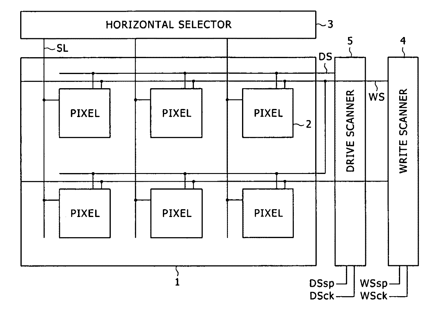
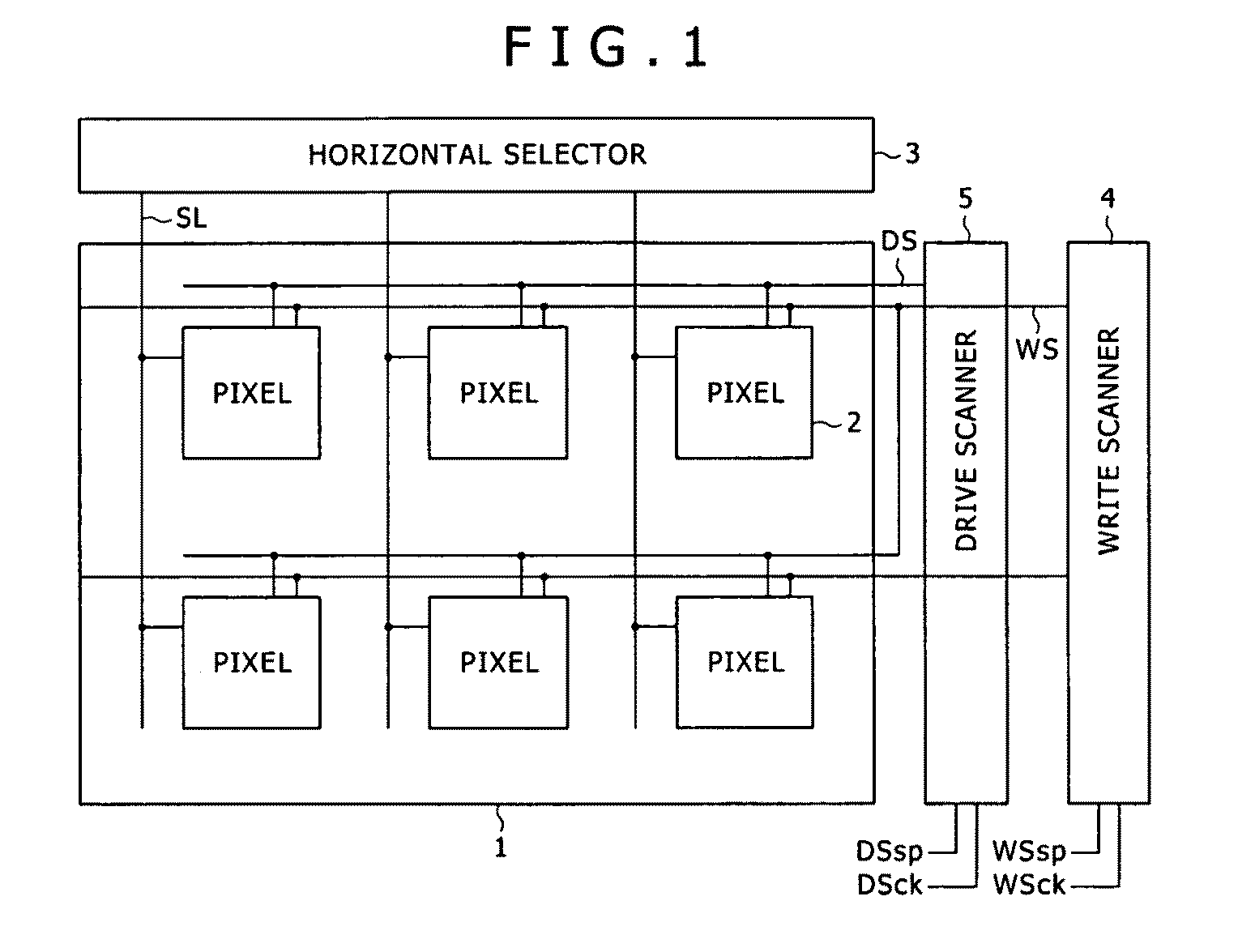
[0059]The preferred embodiment of the present invention will now be described in reference to the accompanying drawings. In the FIG. 1, there is shown a general configuration of a display apparatus according to the present invention. The display apparatus shown includes a pixel array section 1, and driving sections (3, 4 and 5) for driving the pixel array section 1. The pixel array section 1 includes a plurality of scanning lines WS extending along the direction of a row, a plurality of signal lines SL extending along the direction of a column, a plurality of pixels 2 disposed in rows and columns at places at which the scanning lines WS and the signal lines SL intersect with each other, and a plurality of feed lines DS serving as power supply lines disposed corresponding to the rows of the pixels 2. The driving sections 3, 4 and 5 include a controlling scanner (write scanner) 4 for successively supplying a control signal to the scanning lines WS to line-sequentially scan the pixels ...


PUM


Abstract

The present invention provides a display apparatus, includes: a pixel array section including a plurality of scanning lines disposed in rows, a plurality of signal lines disposed in columns, and a plurality of pixels arranged in rows and columns at places at which the scanning lines and the signal lines intersect with each other; and a driving section configured to drive the pixels through the scanning lines and the signal lines; the driving section carrying out block-sequential driving wherein the scanning lines are grouped for each predetermined number to form blocks and the pixels disposed in rows and columns are sequentially driven in a unit of a block and line-sequential driving wherein the scanning lines are scanned in each of the blocks to sequentially drive the pixels in a unit of a row.

Description

CROSS REFERENCES TO RELATED APPLICATIONS[0001]The present invention contains subject matter related to Japanese Patent Application JP 2007-259166, filed in the Japan Patent Office on Oct. 6, 2008, the entire contents of which being incorporated herein by reference.BACKGROUND OF THE INVENTION[0002]1. Field of the Invention[0003]This invention relates to a display apparatus of the active matrix type wherein a light emitting element is used in a pixel and a driving method for a display apparatus of the type described. The present invention relates also to an electronic apparatus which includes a display apparatus of the type described.[0004]2. Description of the Related Art[0005]In recent years, development of a display apparatus of the planar self-luminous type which uses an organic EL (electroluminescence) device as a light emitting element is proceeding energetically. The organic EL device utilizes a phenomenon that, if an electric field is applied to an organic thin film, then the ...

Claims


Application Information

Patent Timeline
Patent Type & Authority Applications(United States)
IPC IPC(8): G06F3/038G09G3/20
CPCG09G3/3291G09G2300/0819G09G2300/0842G09G2300/0866G09G3/3266G09G2310/0283G09G2320/043G09G3/3233G09G2310/0218H01J37/2955
Inventor YAMAMOTO, TETSUROUCHINO, KATSUHIDE
Owner JOLED INC
Why Eureka
Try Eureka