Spike for outdoor lighting fixture

Active Publication Date: 2009-05-14
HUNTER INDUSTRIES
View PDF11 Cites 50 Cited by
  • Summary
  • Abstract
  • Description
  • Claims
  • Application Information

AI Technical Summary

Benefits of technology

[0007]It is an advantage of the present invention to provide a ground spike for supporting a light fixture that has a built-in junction box for protecting the connection and excess cable and keeping them clean.
[0008]It is another advantage of the invention to provide a ground spike that allows the connection to be easily viewed to visually check the integrity of the connection.
[0009]Still another advantage of the invention is provide ready access to the connection for testing and replacement of fixtures or cables.
[0010]In an exemplary embodiment, the present invention comprises a spike for outdoor lighting fixture that includes a receptacle portion integrated into the body of the spike with an open section and a removable transparent window that is configured to enclose the receptacle portion. The transparent window is attached to the receptacle portion using one or more screws or other fasteners. An O-ring seat may be formed along either the edges of the receptacle or the perimeter of the window to retain an O-ring or resilient seal that produces a substantially watertight seal when the window is fastened to the receptacle portion. The spike can include an internally threaded upper portion for receiving a post upon which a lighting fixture is mounted and/or a lamp socket can be attached to the top of the spike and a protective housing fit

Problems solved by technology

The extra cable length can lead to an additional point of vulnerability because it might extend away from the spike, making it vulnerable to damage by someone digging near the spike, for example, replacing plants, where the extended sections of wire would be.
Another problem encountered

Method used


Image

  • Spike for outdoor lighting fixture
  • Spike for outdoor lighting fixture
  • Spike for outdoor lighting fixture

Examples


Embodiment Construction

[0019]The following description sets forth numerous specific details such as examples of specific systems and components, and so forth, in order to provide a good understanding of several embodiments of the present invention. It will be apparent to one skilled in the art, however, that at least some embodiments of the present invention may be practiced without these specific details. In other instances, well-known components or methods are not described in detail in order to avoid unnecessarily obscuring the present invention. Thus, the specific details set forth are merely exemplary. Particular implementations may vary from these exemplary details and still be contemplated to be within the spirit and scope of the present invention.

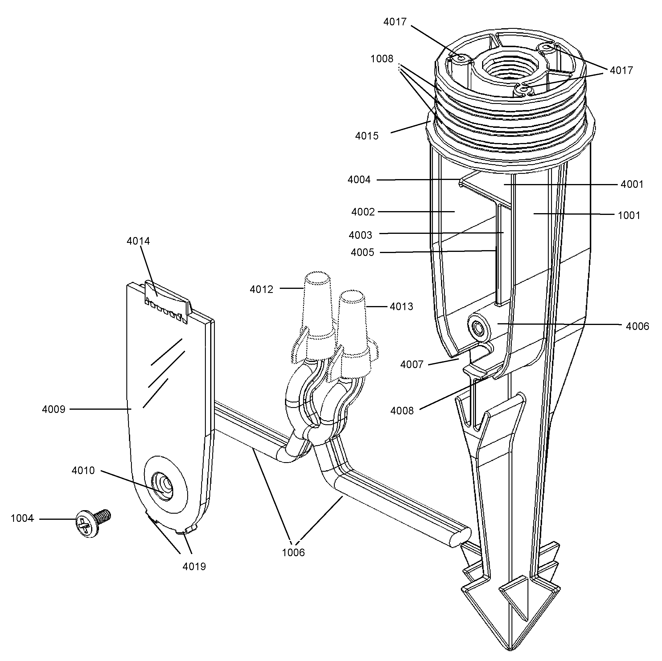
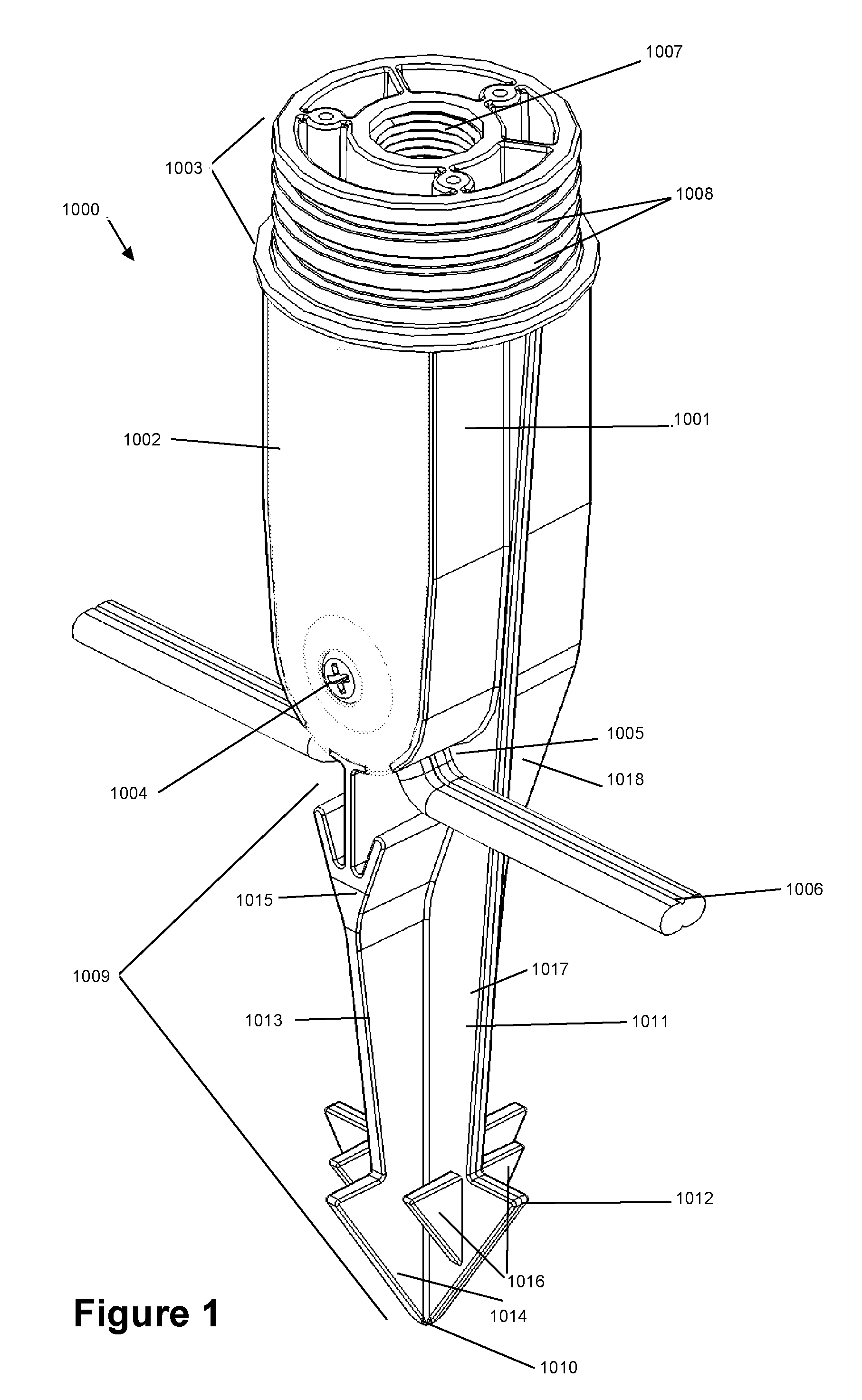
[0020]FIG. 1 is a perspective view of an embodiment of the spike 1000 for outdoor lighting fixtures, which includes a receptacle portion 1001 with a transparent window 1002, an upper portion 1003 for supporting the fixture, and a lower portion 1009 which ...


PUM


Abstract

A spike for outdoor lighting fixture includes a receptacle portion integrated into the body of the spike with an open section and a removable transparent window that is configured to enclose the receptacle portion. The transparent window is attached to the receptacle portion using one or more screws or other fasteners. The spike can include an internally threaded upper portion for receiving a post upon which a lighting fixture is mounted and/or a lamp socket can be attached to the top of the spike and a protective housing fitted around the outer edges of the top of the spike. In a preferred embodiment, the receptacle portion is divided into multiple compartments, e.g., for storing excess cable or spare parts for the fixture, such as wire nuts or lamps, or for securing connection points of a wiring installation. The transparent window permits visual examination of the connection within the receptacle without removing the transparent window.

Description

RELATED APPLICATIONS[0001]This application claims the priority of U.S. Provisional Application No. 60 / 988,065, filed Nov. 14, 2007, which is incorporated herein by reference in its entirety.FIELD OF THE INVENTION[0002]The present invention relates to lighting fixtures for landscape and environmental lighting applications and, more particularly, to devices for securing lighting fixtures at or near the groundBACKGROUND[0003]Outdoor lighting fixtures have been widely adopted for illuminating buildings, gardens, pathways, and entrance ways as the nighttime play of light on the landscape and vegetation can aesthetically pleasing as well as providing sufficient light for safely navigating an otherwise dark walkway. Additionally, such lighting provides enhanced security by eliminating hiding places and unobserved entry points for intruders. The most widely used outdoor lighting systems include one or more low voltage lighting fixtures that are connected to a 12 V transformer that is, in tu...

Claims


Application Information

Patent Timeline
IPC IPC(8): F21V21/00
CPCF21S8/081F21S9/03F21V21/0824Y02B20/72F21V23/00F21V27/00F21W2131/109F21V21/10
Inventor BEADLE, JOSHUA Z.
Owner HUNTER INDUSTRIES
Why Eureka
Try Eureka