
Gas Turbine Engine

Inactive Publication Date: 2009-05-14
NERCESSIAN KEVORK
View PDF0 Cites 2 Cited by
  • Summary
  • Abstract
  • Description
  • Claims
  • Application Information

AI Technical Summary

Benefits of technology

[0015]The importance of less weight and less fuel consumption for gas turbine engines has created the necessity to find a solution allowing the compressor to produce a higher performance of air mass flow / s with less fuel consumption and less weight. Therefore, in one aspect, the invention may provide a gas turbine engine having less weight and less fuel consumption compared to conventional gas turbine engines.
[0063]In yet a further aspect, the contribution of substantially all of the mentioned characteristics results generally in a lower fuel consumption, in a lower emission of gases, less weight, in a lower noise, and less vibrations of the engine.

Problems solved by technology

The dimensions and especially the weights of conventional gas turbine engines, particularly aero turbo engines, have arrived at a limit that does not allow any significant amelioration for better performance without raising the weight of an engine.
An installation of heavier engines brings problems especially for the design and construction of earth bound vehicles, water vehicles, and aircrafts.

Method used


Image

  • Gas Turbine Engine
  • Gas Turbine Engine
  • Gas Turbine Engine

Examples


Embodiment Construction

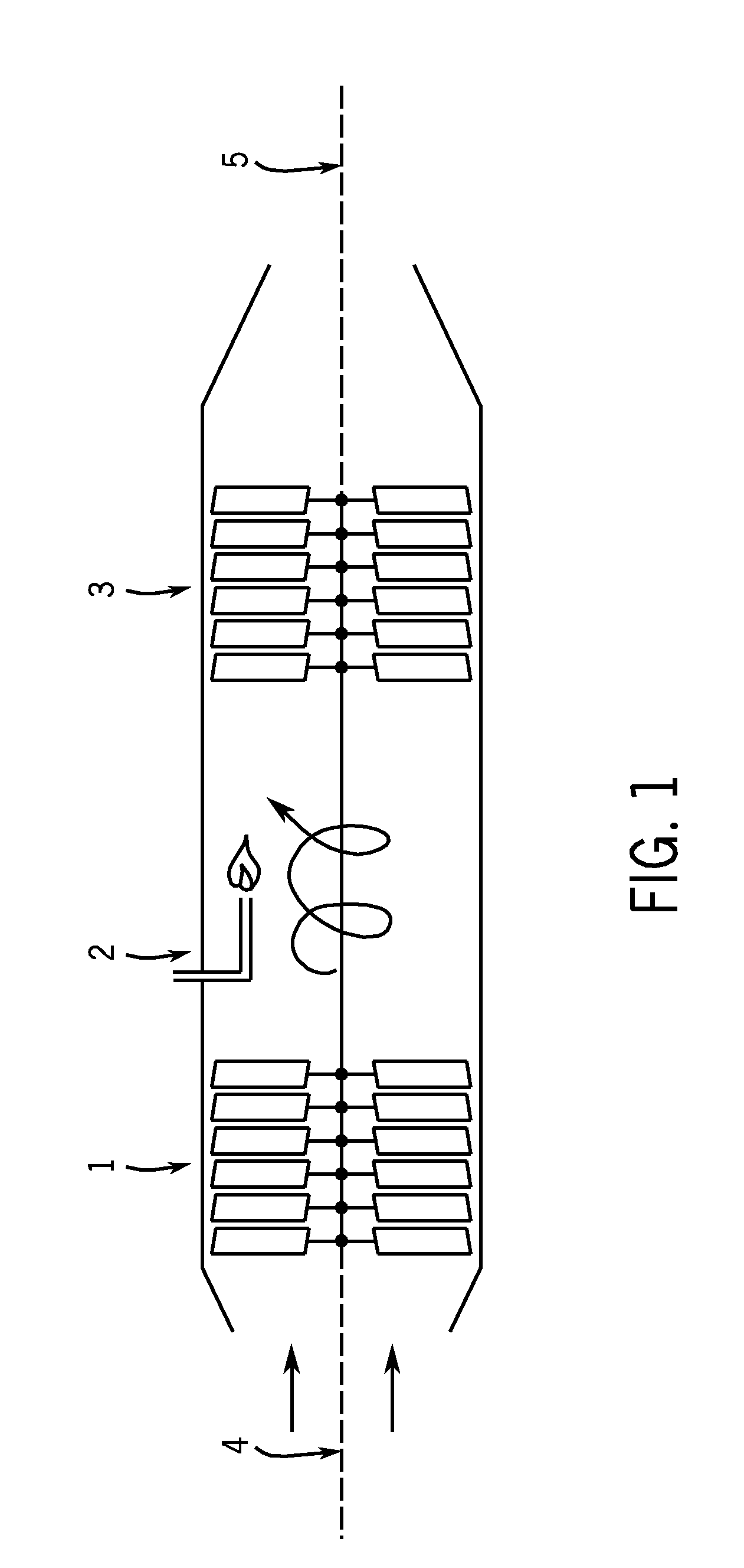
[0074]With initial reference to FIG. 1, FIG. 1 shows the principle of a conventional gas turbine that consists mainly of a compressor 1, a combustion chamber 2, a turbine 3, and a shaft 4, 5. The turbine 3 withdraws substantially all of the energy from the hot gases streaming out of the combustion chamber 2. A part of this energy serves to drive the compressor 1. The rest of the energy may be transmitted to an external device by means of the shaft 4, 5.

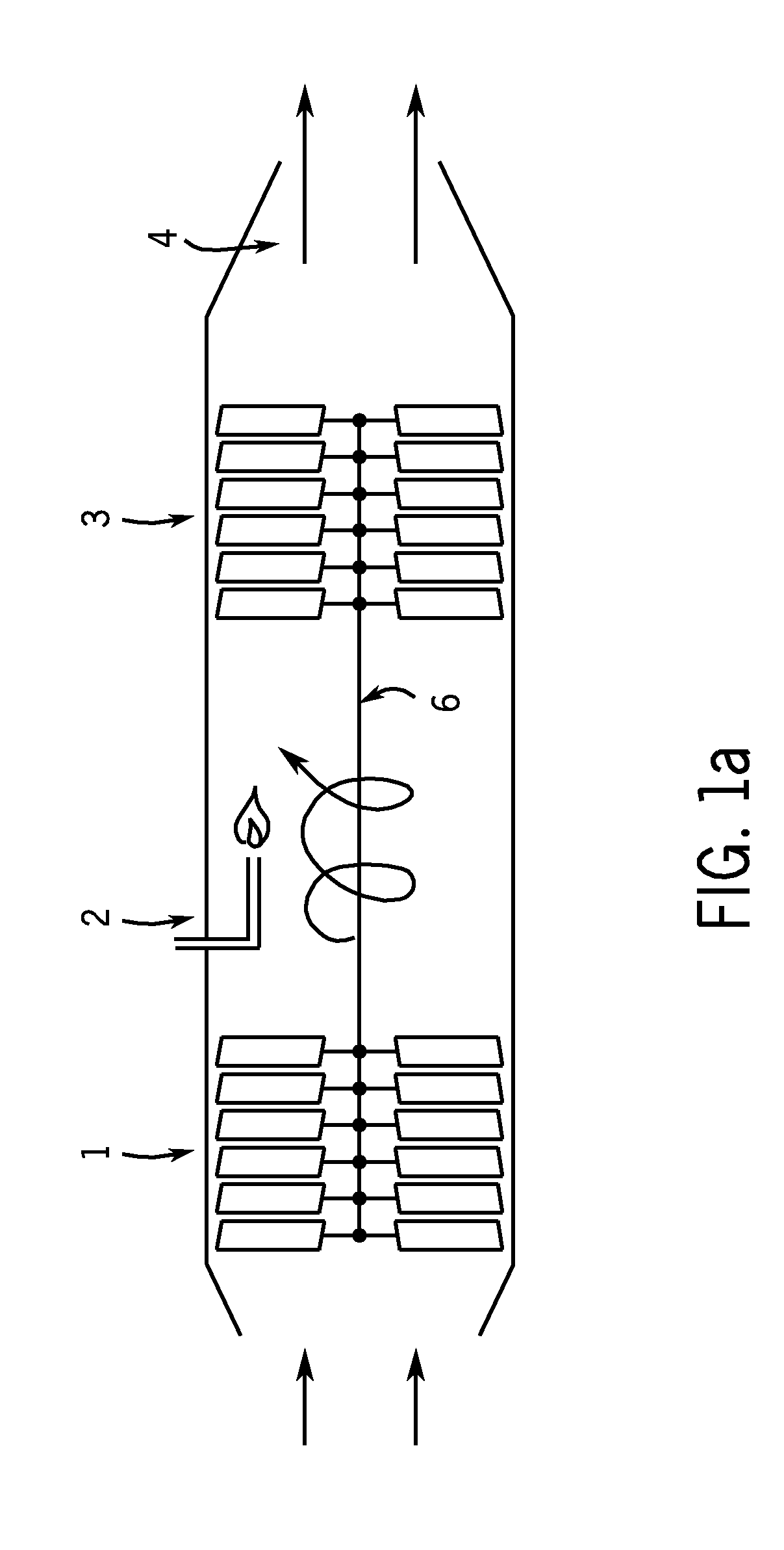
[0075]Turning to FIG. 1a, FIG. 1a shows another application of a conventional gas turbine engine which is an aero turbo engine comprising mainly a compressor 1, a combustion chamber 2, a turbine 3, and an outlet 4. The turbine 3 withdraws from the hot gases streaming out of the combustion chamber 2 the energy required to drive the compressor 1 by means of a shaft 6. The rest of the hot gases streams out of the outlet 4 for the propulsion of an aircraft and the like.

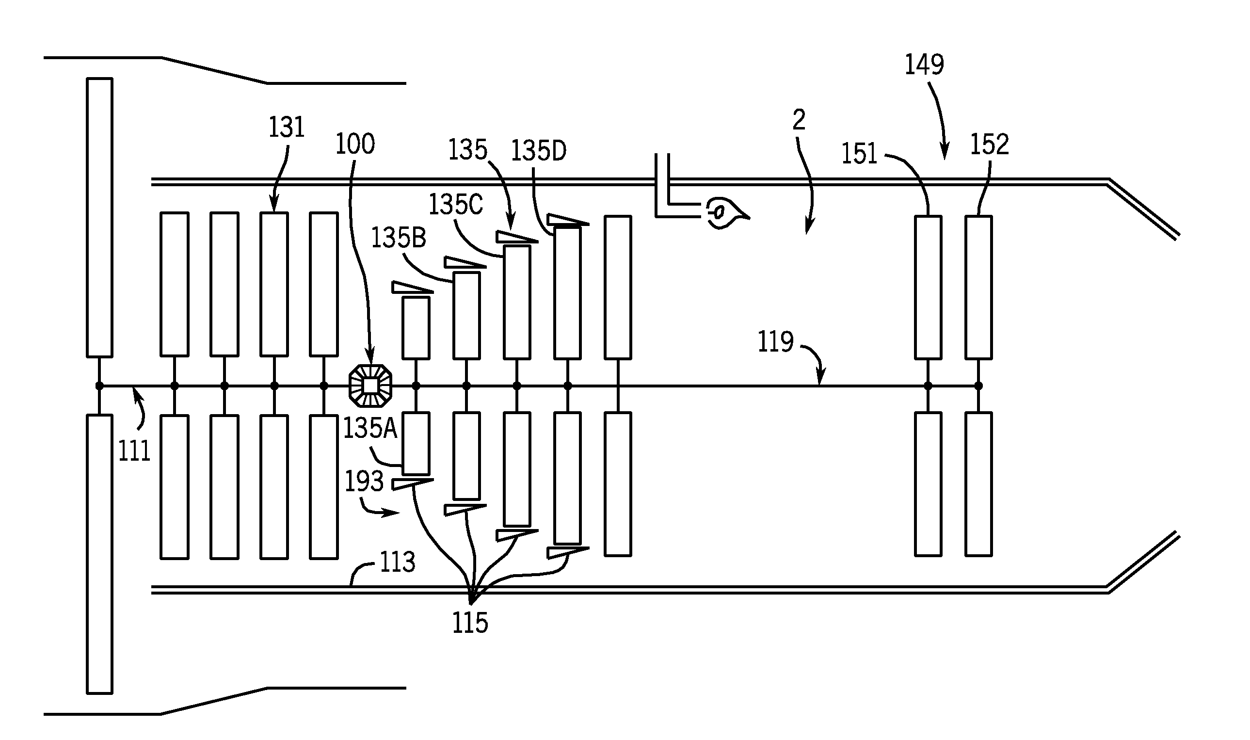
[0076]With specific reference to FIG. 2, FIG. 2 shows a first embodime...


PUM

PropertyMeasurementUnit
Fractionaaaaaaaaaa
Fractionaaaaaaaaaa
Fractionaaaaaaaaaa

Abstract

The invention is directed to a gas turbine engine comprising a compressor, a combustion chamber, and a turbine section installed one after the other in series in the direction of the air and gas flow, wherein the compressor consists of two groups of blade wheels rotating in opposite directions to each other. The deviation of the performance defined as “air mass flow per second” between both compressor groups is minimized and a detachment of the air mass flow from the blades is substantially eliminated. The blade wheels of the second compressor group, beginning at the first blade wheel, are progressively bigger to allow a bypass for the air stream coming from the first compressor group to serve all the blade wheels of the second group essentially simultaneously.

Description

CROSS REFERENCES TO RELATED APPLICATIONS[0001]This application is a continuation-in-part of U.S. patent application Ser. No. 12 / 124,828 filed May 21, 2008 that claimed priority from European Patent Application 07015217.8 filed Aug. 2, 2007, which is hereby incorporated by reference as if fully set forth herein.STATEMENT REGARDING FEDERALLY SPONSORED RESEARCH[0002]Not applicable.BACKGROUND OF THE INVENTION[0003]The invention is directed to gas turbine engines that are a particular form of a combustion engine comprising mainly a compressor, a combustion chamber, and a turbine installed one after the other in the direction of the air and gas flow. In general, the turbine withdraws from the hot stream of gases coming out of the combustion chamber the energy needed to drive the compressor by means of a shaft. By this operation the pressure of the gas stream is reduced approximately by the amount corresponding to the energy withdrawn from the turbine for the compressor.[0004]The two main ...

Claims


Application Information

Patent Timeline
IPC IPC(8): F02C3/067F02C9/20B23P11/00
CPCF01D1/24F02C3/067Y10T29/49321F02K3/06F02K3/072F02C7/36
Inventor NERCESSIAN, KEVORK
Owner NERCESSIAN KEVORK
Learn More