Watt Hour Meter Socket Adapter with Current Transformer Housing Structure

a socket adapter and current transformer technology, applied in the field of socket adapters, can solve the problems of increasing the cost and space requirements of installation, adding current transformer boxes, and presenting a significant danger to the person working on site when bolting and unbolting the meter

Inactive Publication Date: 2009-05-14
AUSTIN RANDY
View PDF9 Cites 31 Cited by
  • Summary
  • Abstract
  • Description
  • Claims
  • Application Information

AI Technical Summary

Benefits of technology

[0017]The adapter is capable of transforming 600 amps of current on the bus bars without another current transformer box on the customer's site. The result is a more efficient, safer, and less costly metering installation.

Problems solved by technology

Of course, adding current transformer boxes adds to the cost and space requirements of the installation.
In any power metering installation, bolting and un-bolting the meter presents a significant danger to the person working on the site.
In certain embodiments, the meter socket carries dangerous current levels that are transformed within the meter itself.
Accordingly, personnel who work on or near that meter socket face grave consequences if they touch a live socket by accident.
Unfortunately, efforts to utilize this technology have required rewiring an existing circuit to install the transformers and then run the transformed current leads to a separate location for metering.
This is quite a bit of work and still requires a technician to deal directly with the high current lines.
The problem with the Preuhs design, as shown in FIG. 17 therein, is that the current transformers are installed in the same housing that connects the meter jaw contacts.
The Preuhs embodiment, therefore, is not safe for currents on the bus bars up to 600 amperes.
Other adapters have been developed for various K-Base metering applications, but these have required large current transformers that do not easily fit within the meter socket without inconveniently shaped housings for the adapter.

Method used


Image

  • Watt Hour Meter Socket Adapter with Current Transformer Housing Structure
  • Watt Hour Meter Socket Adapter with Current Transformer Housing Structure
  • Watt Hour Meter Socket Adapter with Current Transformer Housing Structure

Examples


Embodiment Construction

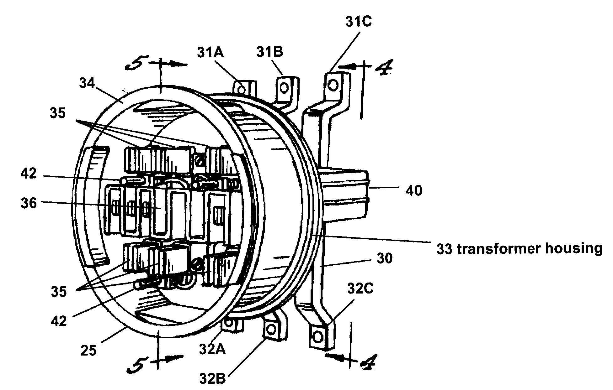
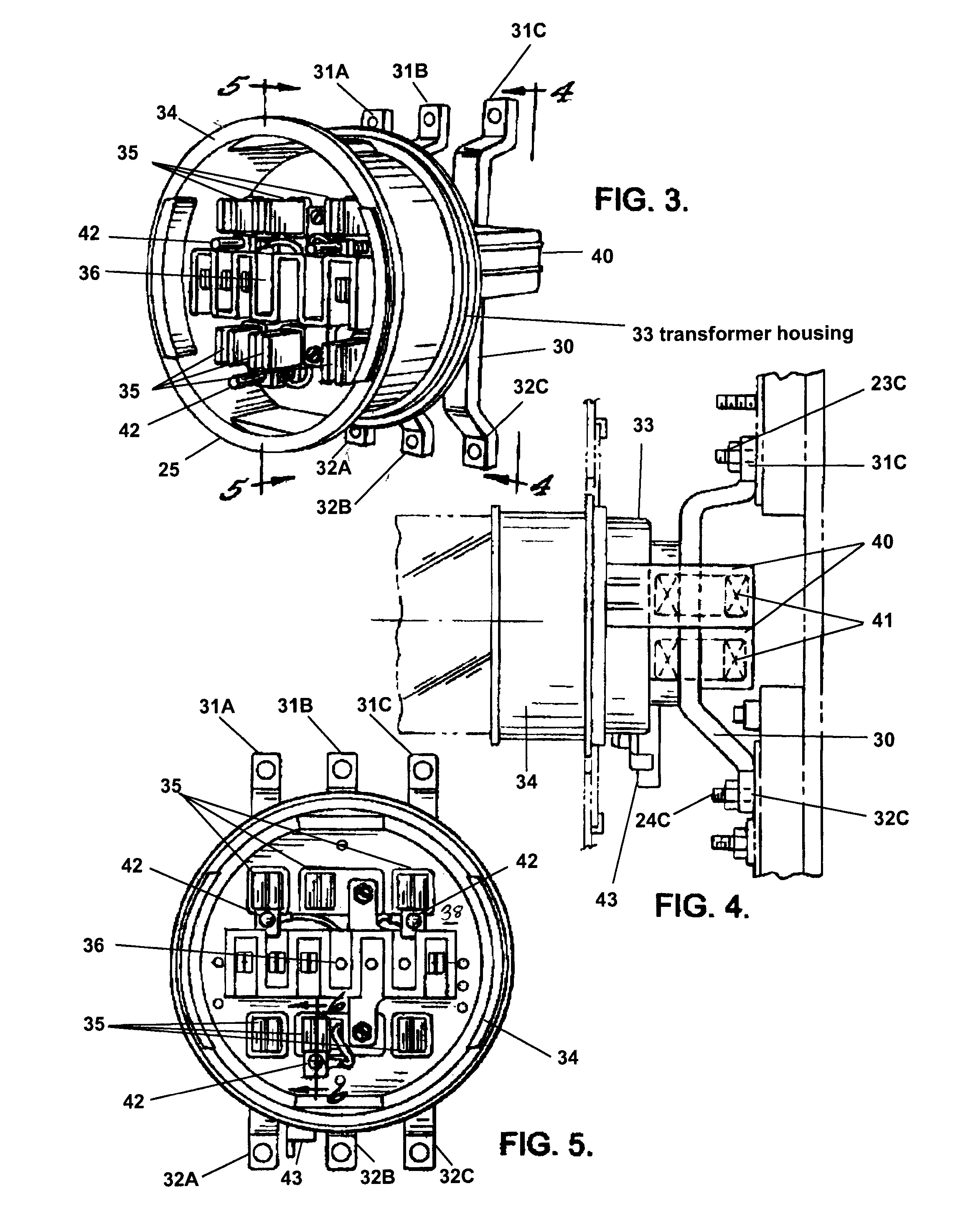
[0029]The meter socket adapter 25 disclosed herein includes safety features previously unknown in the art. These features include, but are not limited to, separable housings for current transformers 41 and jaw contacts 35 allowing for portions of the adapter 25 to be accessed without removing the entire adapter from the circuit. The current transformer housing includes individual insulating compartments 40 for the transformers 41. The transformers 41 need less insulation around the secondary of the transformer 41 because the adapter of this invention includes insulation around the bus bars 30. The secondary of the transformer can be exposed because the transformer 41 is included within an insulating compartment 40 through which the bus bar 30 extends. The smaller transformer body allows for a more precisely measured current transformer housing 33 with dimensions that fit better and more securely within a meter socket 20. In this way, the high currents on the bus bars 30 and the mete...


PUM


Abstract

A meter socket adapter includes an insulating housing that is connected to a power circuit on one side by bus bars and connected to a watt-hour meter on the other side by jaw contacts. The housing includes insulating compartments for current transformers through which the bus bars extend. Current transformers extend around the bus bars and are housed in individual compartments in the current transformer housing. Transformed current is directed to the jaw contacts for metering with the watt-hour meter. The bus bars include an insulating layer there on, reducing the need for insulation around the secondary of the current transformers. The current transformers are then significantly smaller and fit within a K-Base meter socket. The adapter housings define a cavity with separate dielectric plates between the bus bars and the jaw contacts. The adapter conveniently allows for self-contained meters to be used in high current installations.

Description

CROSS-REFERENCE TO RELATED APPLICATIONS[0001]This application is a non-provisional patent application claiming priority to U.S. Provisional Patent Application Ser. No. 60 / 987,032 filed on Nov. 9, 2007, the content of which is incorporated by reference as if fully set forth herein.FIELD OF THE INVENTION[0002]The invention relates to a socket adapter for installing a watt-hour power meter within a circuit providing electricity to a consumer. The invention is particularly useful for installation within a high current circuit and eliminates the need for external current transformers.BACKGROUND OF THE INVENTION[0003]Watt-hour power meters have been known in the art of electric power conduction for many years. In a typical embodiment, a building such a commercial establishment has incoming current from a utility power network. This current passes through a meter socket adapted to attach a watt-hour meter to the circuit for measuring and billing power consumption. The power line from the u...

Claims


Application Information

Patent Timeline
Patent Type & Authority Applications(United States)
IPC IPC(8): H01R33/945
CPCH01R33/945G01R11/04
Inventor AUSTIN, RANDY
Owner AUSTIN RANDY
Why Eureka
Try Eureka