Stack damper

a damper and stout technology, applied in lighting and heating apparatus, ventilation systems, heating types, etc., can solve the problems of increasing the associated energy costs required to run the facility, large constant volume of air to be discharged,

Inactive Publication Date: 2009-05-14
RUSKIN COMPANY
View PDF5 Cites 134 Cited by
  • Summary
  • Abstract
  • Description
  • Claims
  • Application Information

AI Technical Summary

Problems solved by technology

One problem presented by this regulatory regime is the large constant volume of air which must be discharged to maintain proper velocity.
This in turn substantially increases the associated energy costs required to run the facility, even though the percentage of entrained contaminants may be very small.

Method used


Image

  • Stack damper
  • Stack damper
  • Stack damper

Examples


Embodiment Construction

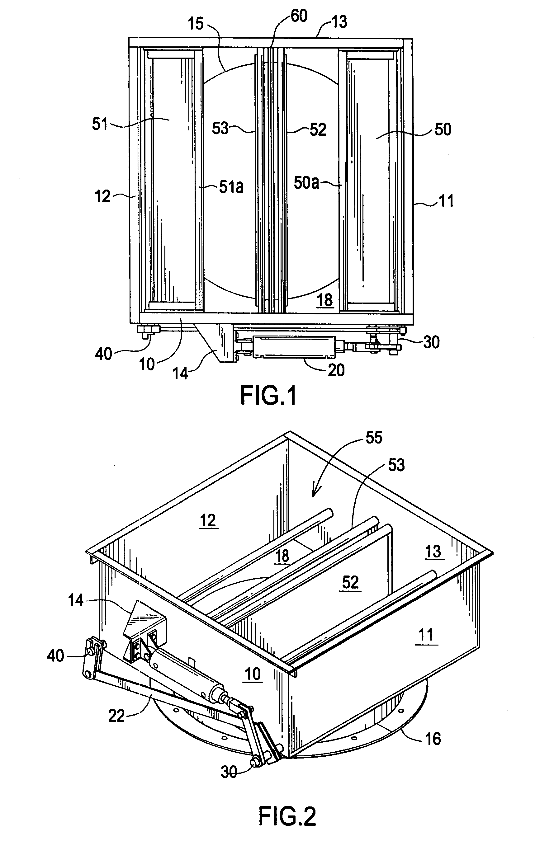
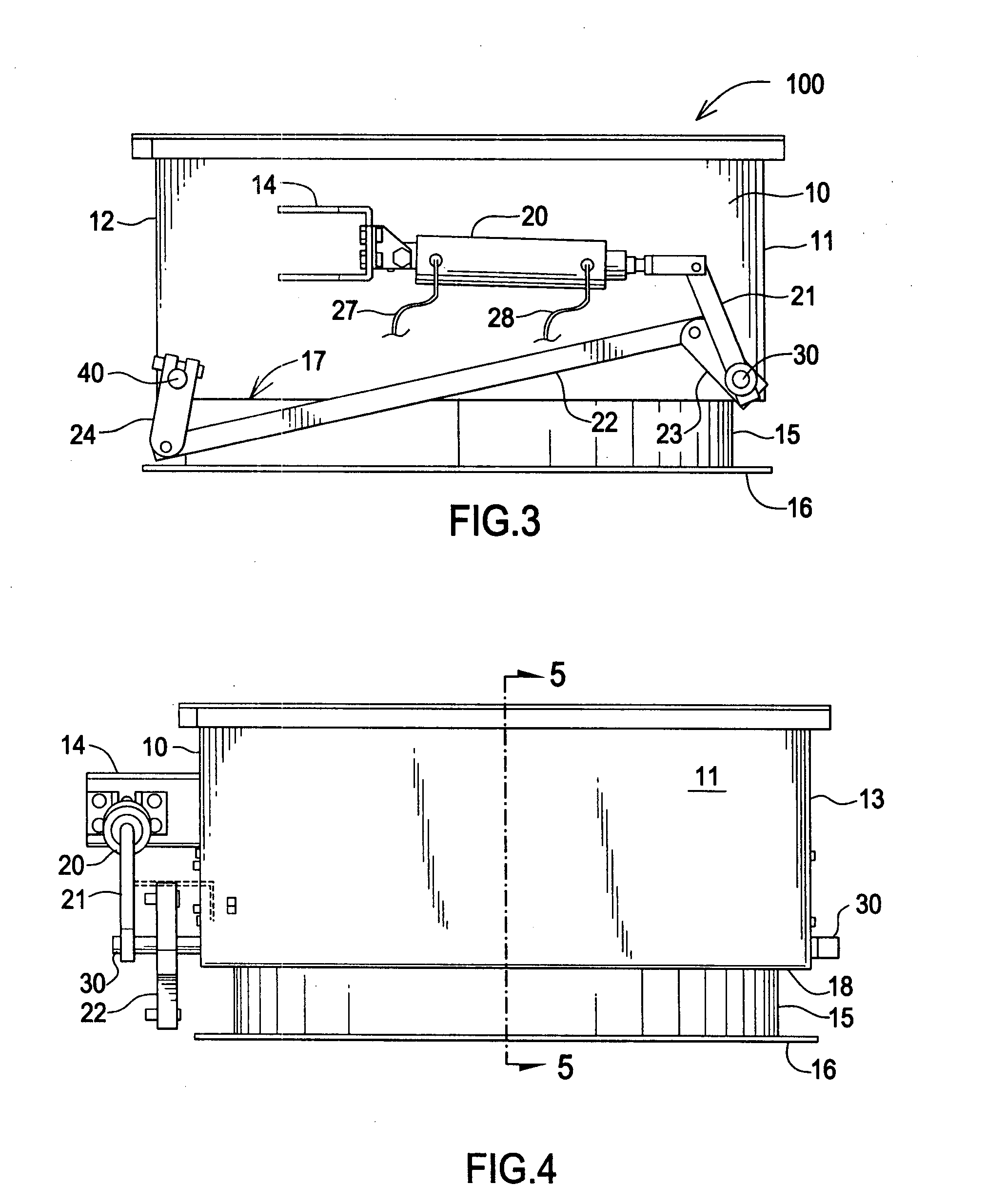
[0022]FIG. 1 is a plan view of the damper. Damper 100 comprises a duct defining an air flow path and generally having sides 10, 11, 12, and 13 arranged in any form suitable for installation in air handling system ductwork. Sides 10, 11, 12, 13 are connected together in a substantially air tight manner to avoid air leakage. Mounting member 14 is attached to side 10. An end of air piston 20 is connected to mounting member 14. Sides 10, 11, 12, 13, 14 and skirt 15 and flange 16 preferably comprise galvanized metal, but may also comprise any other material suitable for HVAC service. Portion 18 is disposed between sides 10, 11, 12, and 13 and skirt 15.

[0023]Damper blade 50 is attached in a cantilever fashion to damper shaft 30. Damper blade 51 is attached in a cantilever fashion to damper shaft 40. Vane 52 is fixedly connected between sides 10 and 13. Vane 52 is fixedly connected between sides 10 and 13. Vanes 52 and 53 are substantially parallel. Damper blades 50 and 51 are substantiall...


PUM


Abstract

A damper comprising a duct defining an air flow path, opposing damper blades pivotally mounted within the duct, each damper blade having an end that is pivotally mounted in cantilevered fashion in the duct so that an opposing end is free to move within the duct, wherein each damper blade is planar in shape, cooperating flow straightening members disposed centrally in the air flow path, an air flow sensor for generating a signal cooperatively disposed between the flow straightening members, and an actuator for pivoting each damper blade within the duct in response to the signal from the air flow sensor to vary the damper blade position and thereby maintain a desired velocity of air exiting the damper.

Description

FIELD OF THE INVENTION[0001]The invention relates to a stack damper, and more particularly, to a stack damper which automatically maintains a downstream air flow velocity by adjusting a damper blade position in response to an air flow signal.BACKGROUND OF THE INVENTION[0002]Suitable air flow velocity is a widely accepted means of maintaining entrainment of air borne contaminants. To this end various environmental rules require that air exiting from an exhaust stack or duct be discharged into the air at a predetermined height (or some calculated distance from intake ducts) and a predetermined velocity to ensure proper diffusion.[0003]One problem presented by this regulatory regime is the large constant volume of air which must be discharged to maintain proper velocity.[0004]Compounding the problem is the volume of air which is required to be discharged varies during the day. For instance, the volume of discharged air could be reduced dramatically during off hours. On the other hand, ...

Claims


Application Information

Patent Timeline
Patent Type & Authority Applications(United States)
IPC IPC(8): F24F13/16F24F13/10
CPCF24F11/04F24F2011/0042F24F2011/0038F24F13/1413F24F2110/30F24F2110/40F24F11/74
Inventor VAN BECELAERE, ROBERT M.
Owner RUSKIN COMPANY
Why Eureka
Try Eureka