Push-Pull Chain and Actuator

Active Publication Date: 2009-05-14
WINDOWMASTER
View PDF9 Cites 22 Cited by
  • Summary
  • Abstract
  • Description
  • Claims
  • Application Information

AI Technical Summary

Benefits of technology

[0027]It is yet another object of the invention to provide push-pull chain actuator with an improved mechanical efficiency. This object is achieved in accordance with claim 36 by providing an actuator with a chain according to any of claims 19 to 35, an actuator housing provided with a chain path in communication with a chain exit opening, the chain in its retracted position being at least partially received in the chain path, with

Problems solved by technology

The maximum thrust load of the actuator is often limited by the maxim

Method used


Image

  • Push-Pull Chain and Actuator
  • Push-Pull Chain and Actuator
  • Push-Pull Chain and Actuator

Examples


Embodiment Construction

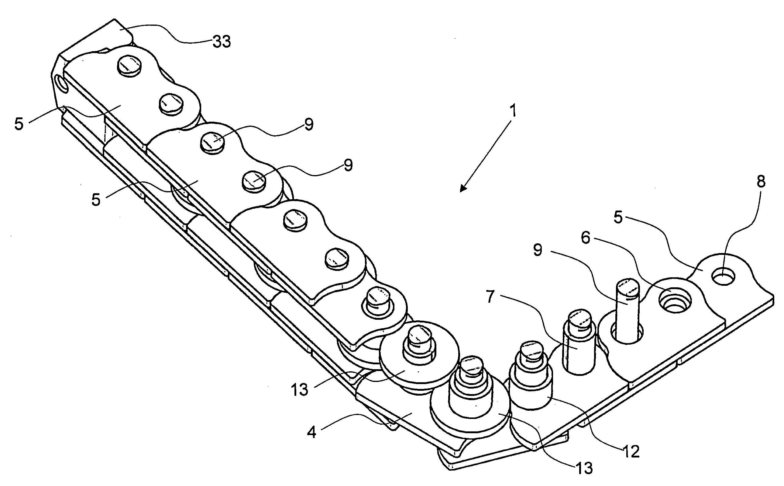
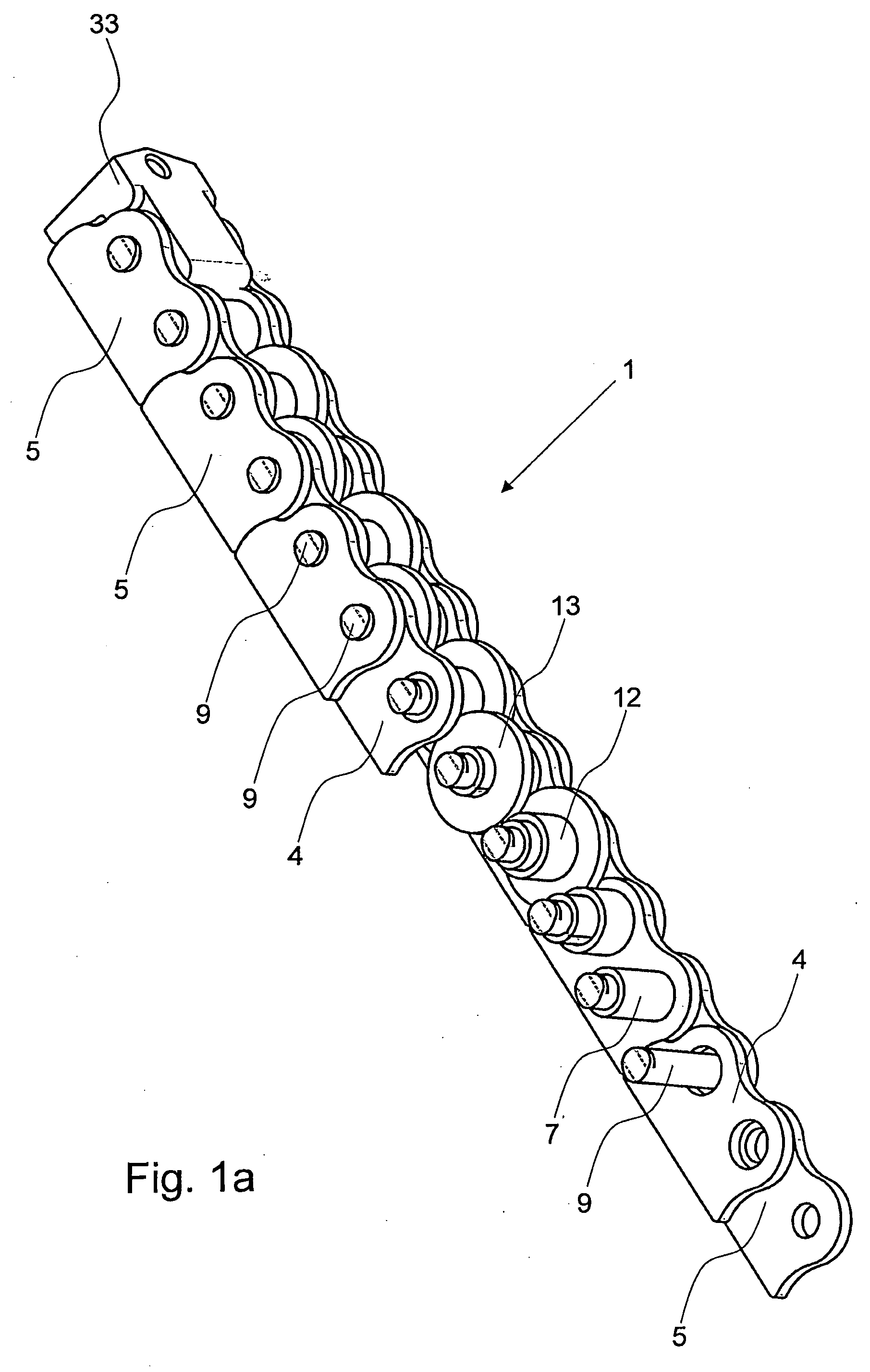
[0049]FIGS. 1a to 1d, 2 and 3 illustrate a chain according to a first preferred embodiment of the invention. The chain 1 is composed of pairs of inner links 4 and outer links 5. The inner and outer links are formed by metal plates that are preferably manufactured in a die stamping process.

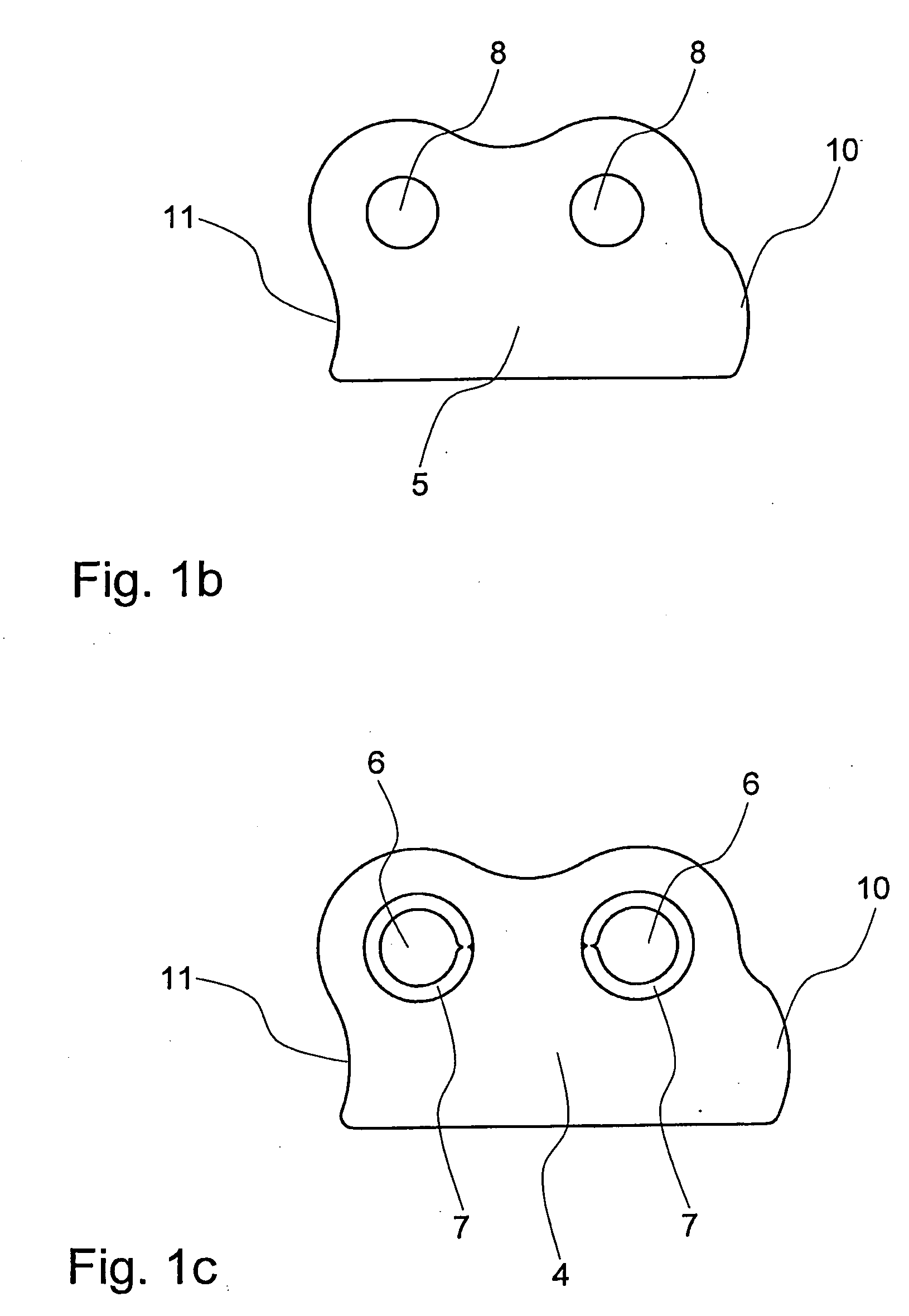
[0050]The inner links 4 are provided with pairs of holes 6 that receive bushings 7 connecting the pairs of inner links. The outer links 5 are provided with pairs of holes 8 that receive driving pins 9 connecting the pairs of outer links. The driving pins 9 are rotably received inside the bushings 7 and thus hinge the pairs of inner links 5 to the pairs of outer links 5.

[0051]The holes 6,8 are offset to one side in the height of the links 4,5 and projections 10 on one longitudinal end of the side away from the pins are complementary with the recesses 11 on the opposite end of the adjacent link. When the chain 1 is straight as shown in FIG. 1 the projections 10 abut with the recesses 11. The links th...


PUM

PropertyMeasurementUnit
Pressureaaaaaaaaaa
Diameteraaaaaaaaaa
Widthaaaaaaaaaa

Abstract

A push-pull chain (1) that can bend in one direction only, and is provided with at least two rollers (12,13) on each of the driving pins, one of the rollers (12) engages a drive sprocket (29) and the other of said at least two rollers (13) engages a chain guide surface (28). An actuator (20) for e.g. opening and closing a window that uses this dual-roller push-pull chain. A link (105) driven push-pull chain (101) that can bend in one direction only, with links (105) that is shaped as an engagement surface for engaging a drive sprocket (129). An actuator (120) for e.g. opening and closing a window that uses the link driven push-pull chain.

Description

[0001]The present invention relates to push-pull chains for use in actuators, in particular to push-pull chains that can bend in direction only. The invention also relates to an actuator that comprises such a push-pull chain.BACKGROUND ART[0002]DE 102 06 274 discloses a push-pull chain formed by a plurality of pairs of inner links and outer links, with alternate pairs of the inner links being sequentially coupled to alternate pairs of outer links by parallel driving pins with rollers. The ends of the links are provided with faces which abut in a manner to prevent the chain from bending by rotation of the links about their hinges in one direction but allow the chain to bend freely in the other direction. The faces have a complementary shape to each other so that, when the chain is under pressure, they lie directly against each other to prevent a bending movement. The chain can be used in an actuator with a chain path leading to a chain exit and guiding the chain past a sprocket that ...

Claims


Application Information

Patent Timeline
IPC IPC(8): F16G13/20F16H27/02F16G13/18
CPCY10T74/1884F16G13/20
Inventor SOERENSEN, JENS JOERREN
Owner WINDOWMASTER
Why Eureka
Try Eureka