Bladeset for a hair cutting apparatus

a hair cutting and blade technology, applied in the direction of metal working devices, etc., can solve the problems of hair still overloading or becoming caught in the blade cavity, the blade stalling, and the hair can still be separated or failed to properly cut hair, so as to reduce the overload effect, increase the density of teeth, and reduce the effect of overload

Active Publication Date: 2009-05-21
WAHL CLIPPER
View PDF28 Cites 29 Cited by
  • Summary
  • Abstract
  • Description
  • Claims
  • Application Information

AI Technical Summary

Benefits of technology

[0007]The above-listed needs are met or exceeded by the present bladeset for a hair clipper, which features a moving blade having an increased density of teeth with respect to the stationary blade for providing more efficient hair cutting and reducing overload effects. In the preferred embodiment, there are at least twice as many teeth on the moving blade as on the stationary blade, enabling at least 1½ as many cutting actions per stroke than current hair clippers. The present bladeset also includes a moving blade having a staggered tooth design for distributing the cutting load across a width of the moving blade. In the preferred embodiment, the moving blade teeth have a substantially flat tip and a continuous square cross-section from root to tip for enabling hair to properly enter and remain within the cutting zone. In addition, an angle between respective cutting edges of the stationary blade teeth and the moving blade teeth is reduced due to the geometry of the teeth, further increasing cutting efficiency.

Problems solved by technology

In current hair clippers, a common side effect of such rapid movement is that the bladeset becomes overloaded with hair, which can cause the blades to stall, separate or fail to properly cut the hair.
Hair clippers having a moving blade including long and short teeth alternately arranged along the blade have been developed but are typically not known to reduce these overload effects.
Although the staggered tooth design in Need distributes the cutting load between the long and short teeth, the number of cuts per reciprocation of the moving blade is not changed, and accordingly, during increased clipper feed rates, hair can still overload or become caught in the blade cavities.

Method used


Image

  • Bladeset for a hair cutting apparatus
  • Bladeset for a hair cutting apparatus
  • Bladeset for a hair cutting apparatus

Examples


Embodiment Construction

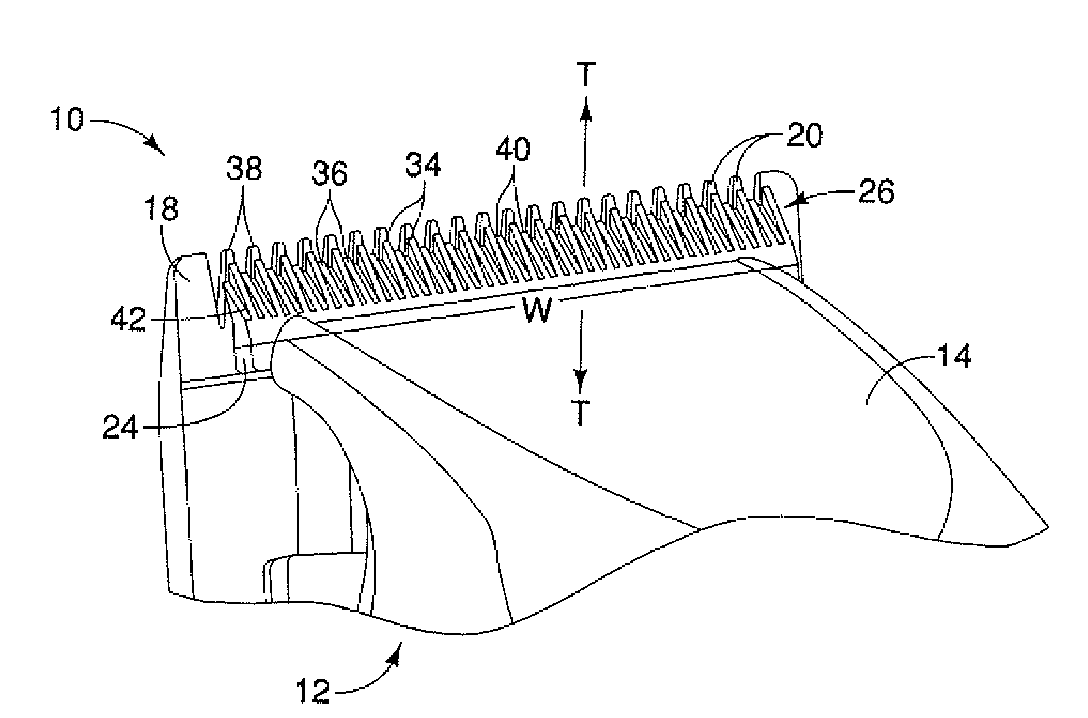
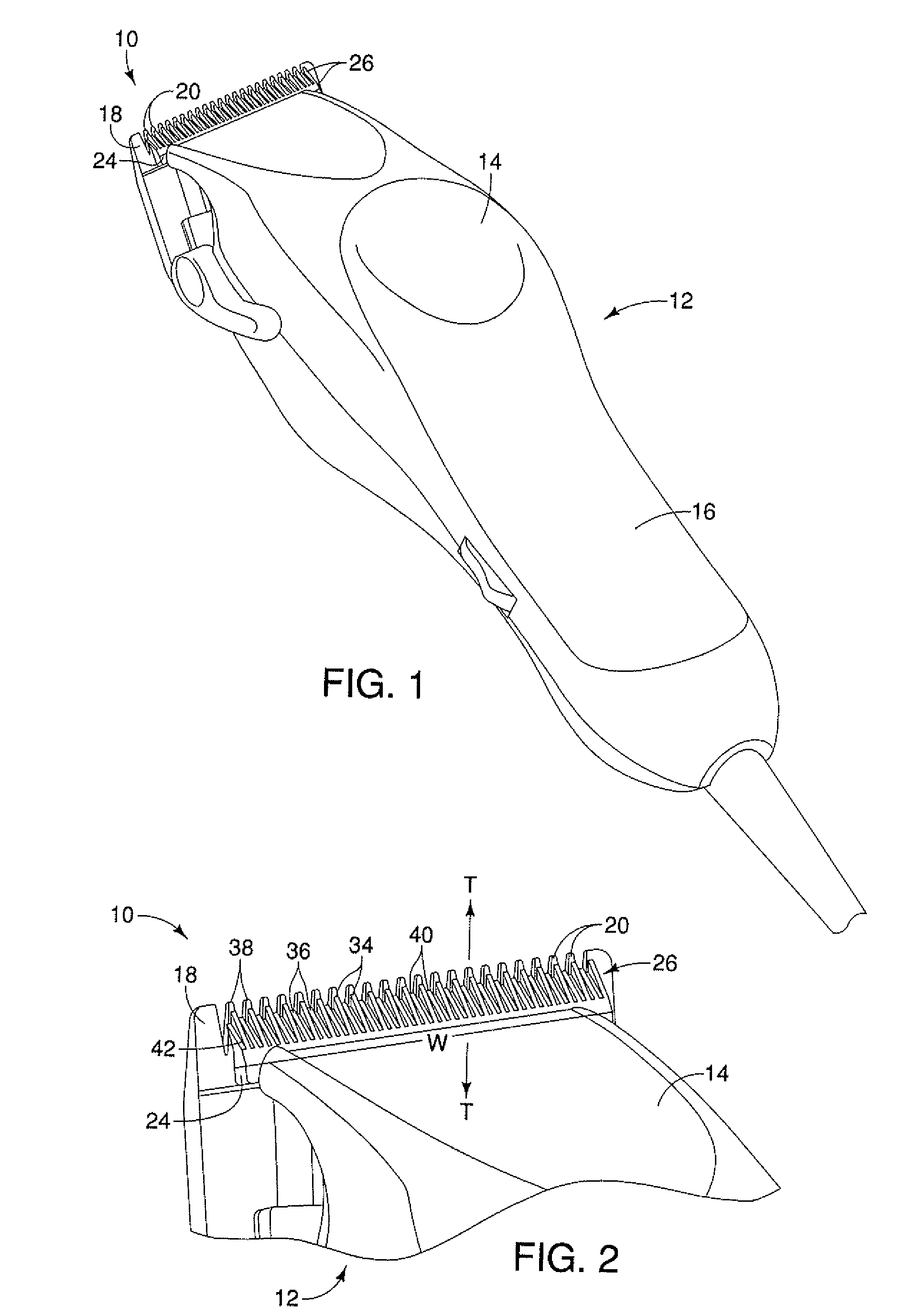
[0013]Referring now to FIG. 1, a hair clipper bladeset is provided and generally designated 10. As known in the art, the bladeset 10 is attached to a hair clipper 12 including a housing 14 having a generally elongate handle 16. The housing 14 generally encloses an electric motor and drive system (not shown) operatively connected to the bladeset 10.

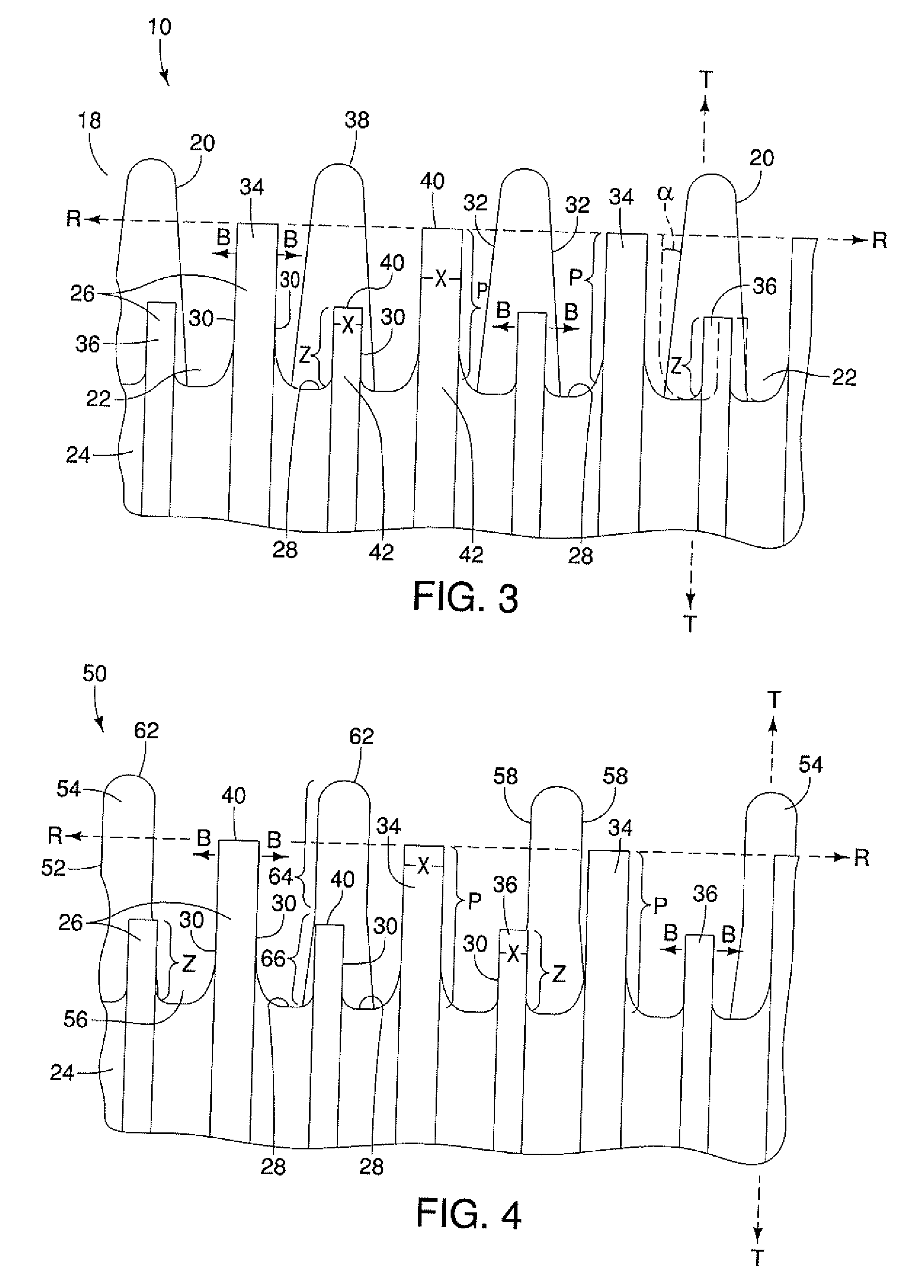
[0014]As seen in FIGS. 1-3, the bladeset 10 includes at least one stationary blade 18 having a plurality of stationary blade teeth 20 defining stationary blade teeth cavities or spaces 22 between adjacent teeth, and at least one moving blade 24 having a plurality of moving blade teeth 26 defining moving blade teeth cavities or spaces 28 between adjacent teeth. The stationary blade 18 is connected to the housing 14 by any suitable fastening technology, such as screws or the like (not shown). The moving blade 24 is configured for laterally reciprocating relative to the stationary blade 18 for cutting hair therebetween in a scissors action, a...


PUM


Abstract

A bladeset for a hair clipper includes at least one stationary blade having a plurality of stationary blade teeth, and at least one moving blade having a plurality of moving blade teeth and being configured for laterally reciprocating relative to the at least one stationary blade for cutting hair therebetween, the moving blade having a set of long teeth configured for cutting hair across a width of said moving blade, and a set of short teeth configured for cutting hair across said moving blade width when a clipper feed rate exceeds a given speed.

Description

BACKGROUND OF THE INVENTION[0001]The present application relates to electric or battery-operated hair cutting appliances such as hair clippers, hair trimmers, and more particularly, to a bladeset for such devices.[0002]Electric and battery-operated hair clippers are well known to hair styling professionals and laymen alike, and generally include a bladeset having a moving blade reciprocating with respect to a stationary blade. Typically, each blade has a row of teeth projecting from an edge along a width of the blade such that the opposing rows of the moving and stationary blades are arranged substantially parallel to and in contact with each other. While variations in blade tooth configuration are known, in some conventional hair clippers, the teeth on each blade extend approximately the same distance from their respective blades, such that the tips of the teeth generally define a straight line. Generally, V-shaped cavities are formed between adjacent blade teeth for receiving the ...

Claims


Application Information

Patent Timeline
Patent Type & Authority Applications(United States)
IPC IPC(8): B26B19/02B26B19/00
CPCB26B19/3846
Inventor MELTON, SCOTT A.
Owner WAHL CLIPPER
Why Eureka
Try Eureka