
Dual-stage centring magnetic bearing

a magnetic bearing and double-stage technology, applied in the direction of magnetic bearings, instruments, cosmonautic vehicles, etc., can solve the problems of significant radial bulk, drawback related to the radial bulk of the magnetic bearing, and still present drawbacks

Inactive Publication Date: 2009-05-21
THALES SA
View PDF7 Cites 12 Cited by
  • Summary
  • Abstract
  • Description
  • Claims
  • Application Information

AI Technical Summary

Benefits of technology

[0016]an excitation circuit making it possible to apply an excitation current to the said windings,
[0019]each winding is wound around an axis of revolution of the winding contained in the mid-plane of the magnetic bearing and passing approximately through the centre of the magnetic bearing, this arrangement of the windings making it possible to utilize the entirety of the windings present in the bearing and, in cooperation with the plurality of magnets, to control the centring of the mobile body with respect to the reference body for translational motions in relation to the first and second reference axes and, in a passive manner, in relation to the axis of revolution of the magnetic bearing.

Problems solved by technology

However, they exhibit, in the state of the art, the drawback of significant radial bulk.
However, the drawback related to the radial bulk of the magnetic bearing is still present, the windings being wound around vertical axes of revolution.

Method used


Image

  • Dual-stage centring magnetic bearing
  • Dual-stage centring magnetic bearing
  • Dual-stage centring magnetic bearing

Examples


Embodiment Construction

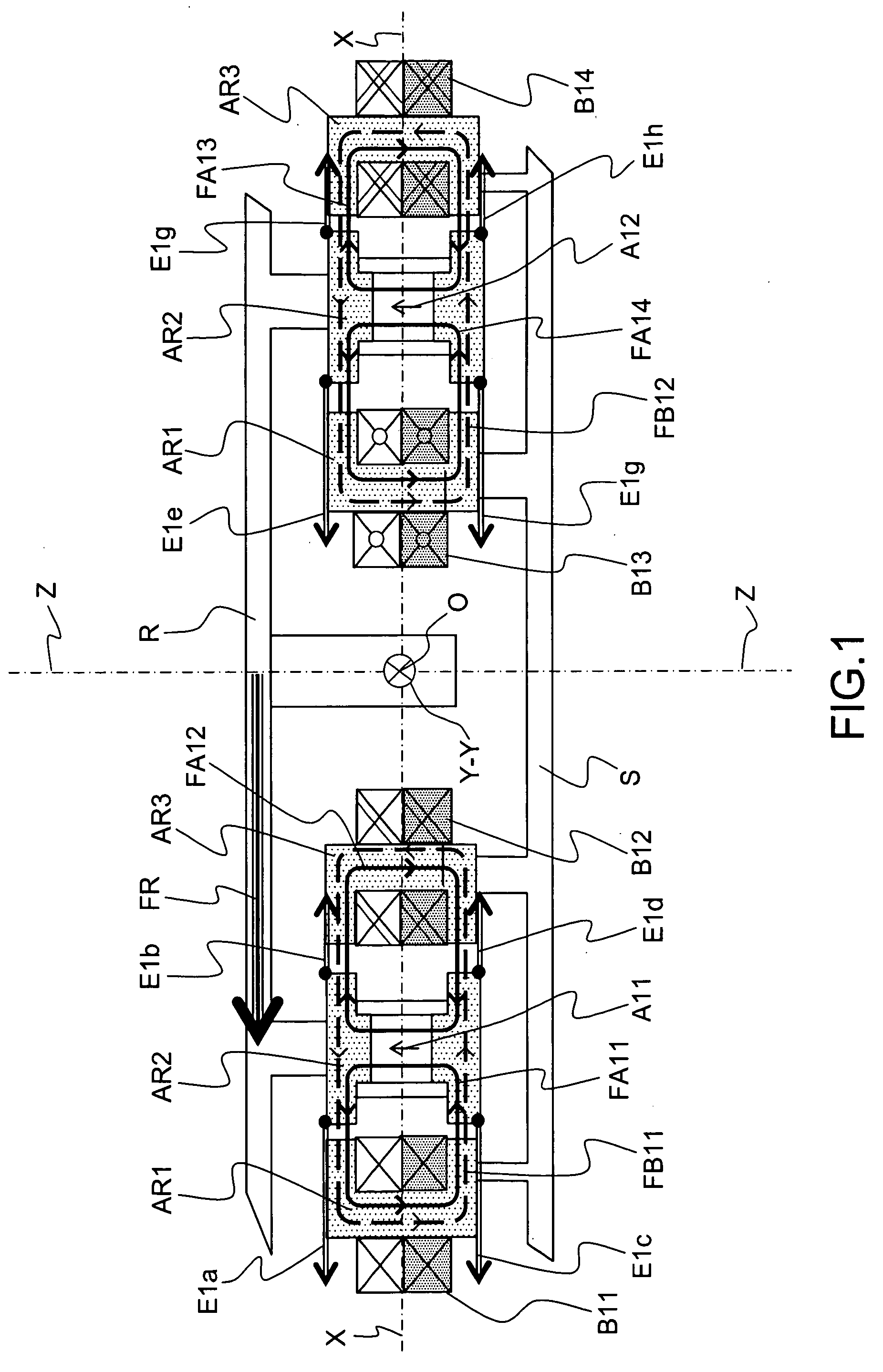
[0028]FIG. 1 presents a diagram of a centring magnetic bearing structure of the state of the art. This magnetic bearing, with centre O, has symmetry of revolution about its axis of revolution Z-Z. It allows the free rotation about the Z-Z axis of the mobile body, or rotor, R with respect to the reference body, or stator, S. The reference axes X-X and Y-Y intersect at the centre of the bearing O and define a mid-plane of the magnetic bearing.

[0029]This bearing comprises three ferromagnetic armatures AR1, AR2 and AR3, again having symmetry of revolution about Z-Z. It is noted that annular air gaps separate the armature AR2 from the armature AR1 on the one hand and from the armature AR3 on the other hand.

[0030]The central armature AR2 comprises a plurality of magnets A11, A12 distributed annularly in a homogeneous manner; these magnets A11, A12 exhibit the same direction of magnetization. The armatures AR1 and AR3 support a plurality of windings B11, B12, B13, B14 also distributed annu...


PUM


Abstract

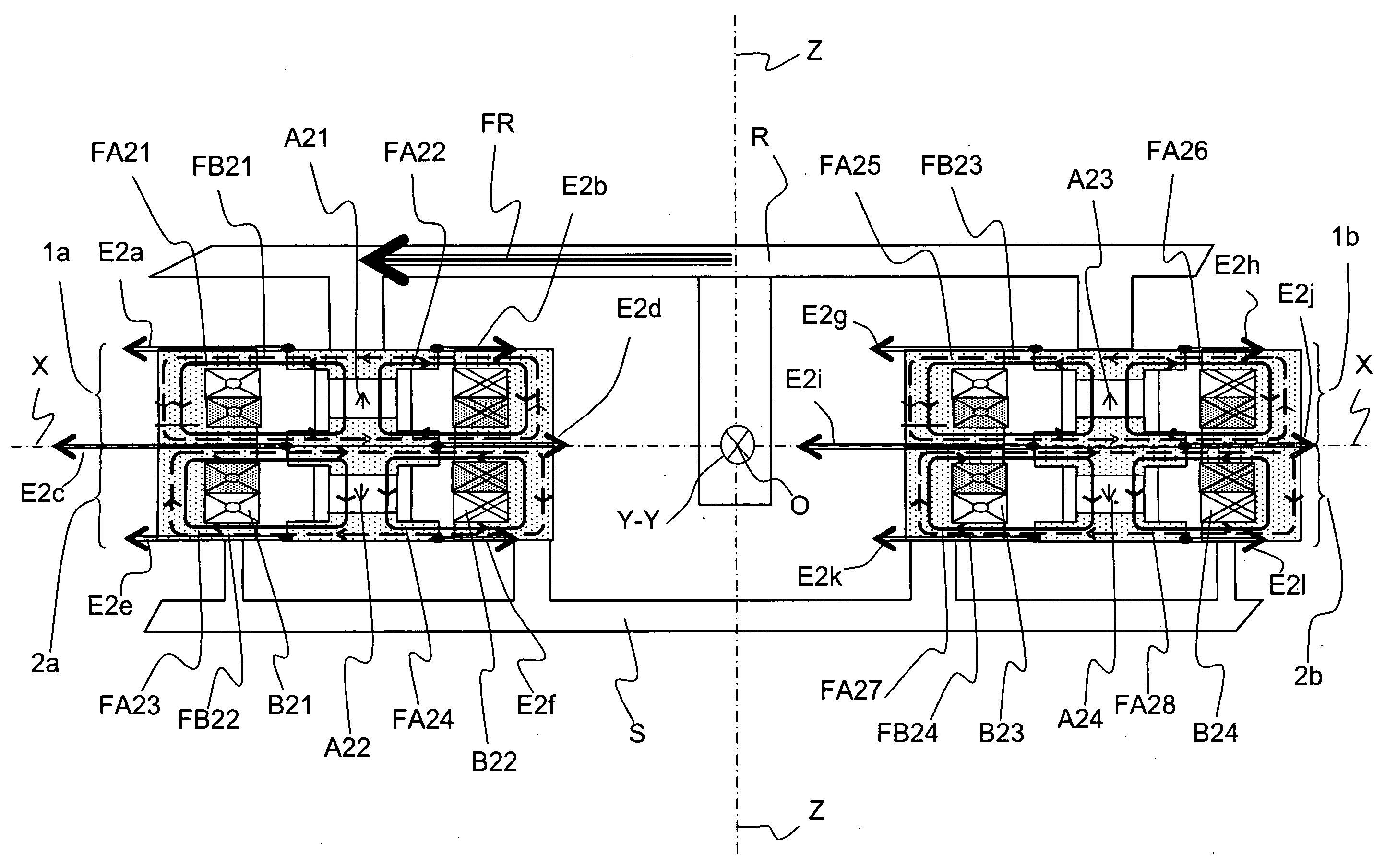
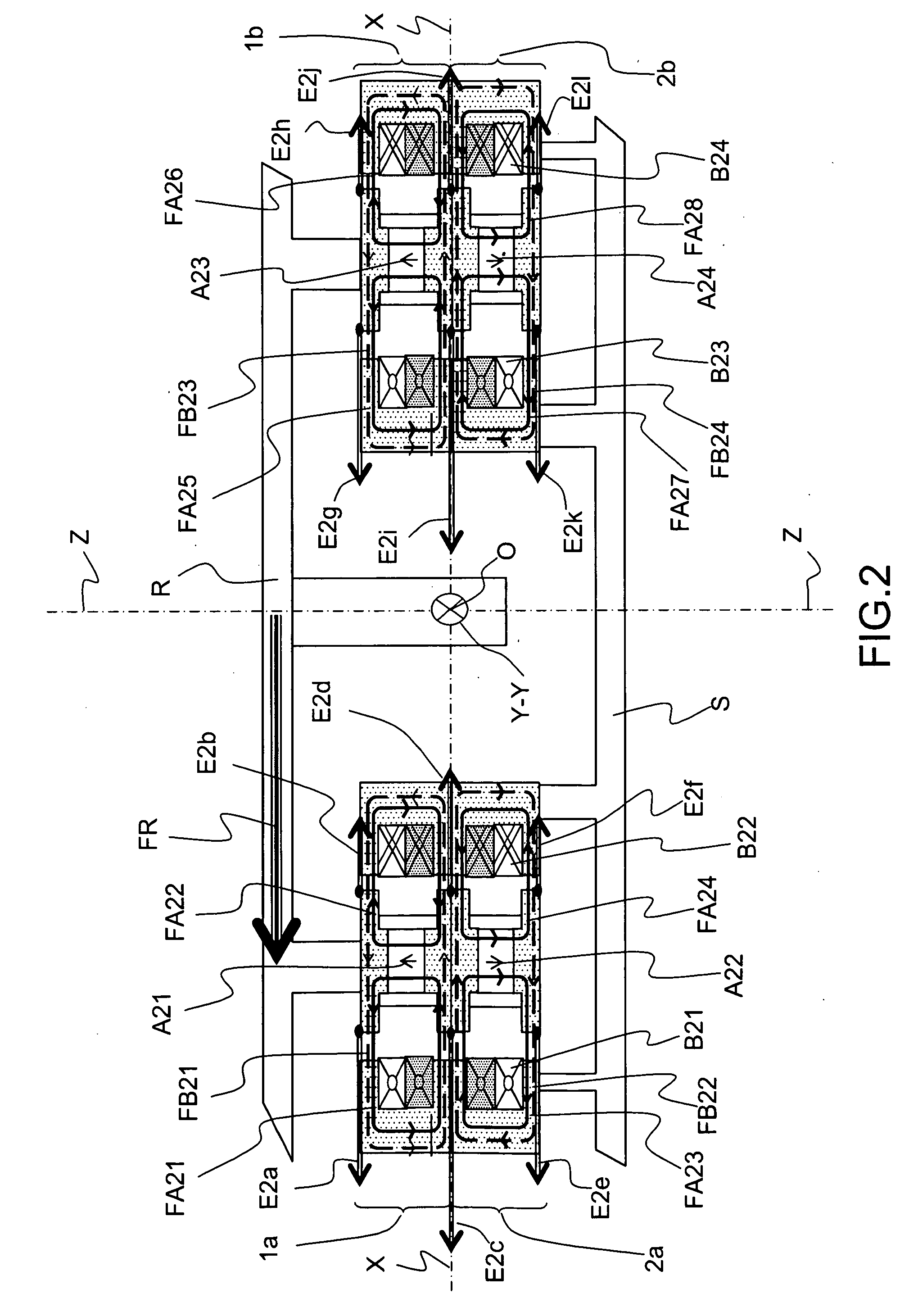
The present invention relates to a magnetic centring structure, and more particularly a structure of a centring magnetic bearing intended notably for space applications. The solution proposed in the present patent is suited to the centerers used on gyroscopic wheels and actuators. The main originality of the invention is the proposal of a dual-stage magnetic bearing structure. According to the implementation chosen, this invention presents the significant advantage of an improvement in terms of radial bulk.

Description

RELATED APPLICATIONS[0001]The present application is based on, and claims priority from, French Application Number 07 08054, filed Nov. 16, 2007, the disclosure of which is hereby incorporated by reference herein in its entirety.FIELD OF THE INVENTION[0002]The present invention relates to a magnetic centring structure, and more particularly to a structure of a centring magnetic bearing intended notably for space applications.[0003]The solution proposed in the present document is suited to the centerers used on gyroscopic wheels and actuators.BACKGROUND OF THE INVENTION[0004]Various magnetic centring structures are known. They generally rely on the use of permanent magnets, windings, ferromagnetic armatures and, usually, an electrical excitation circuit making it possible to control the magnetic fluxes generated by the windings. The role of a centring magnetic bearing is to centre a mobile body with respect to a reference body. Several motions of the mobile body with respect to the r...

Claims


Application Information

Patent Timeline
IPC IPC(8): G01C19/24H02K7/09
CPCB64G1/286F16C32/0465Y10T74/125F16C32/0487F16C32/048F16C2326/47
Inventor CHASSOULIER, DAMIEN
Owner THALES SA
Learn More