
U-shaped burner for grill

a burner and grill technology, applied in the field of grill burners, to achieve the effect of improving the flame coverage area

Inactive Publication Date: 2009-05-21
GEOGLOBAL PARTNERS
View PDF27 Cites 0 Cited by
  • Summary
  • Abstract
  • Description
  • Claims
  • Application Information

AI Technical Summary

Benefits of technology

[0004]An object of the present invention is to provide an improved burner having a U-shaped configuration which improves flame coverage area along the entire length of the burner.
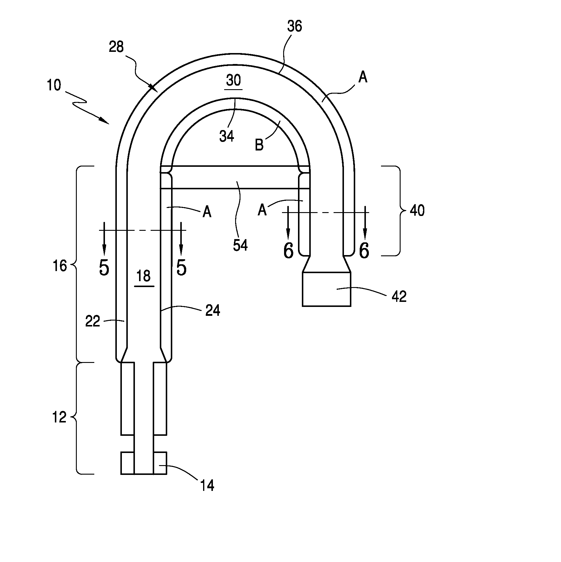
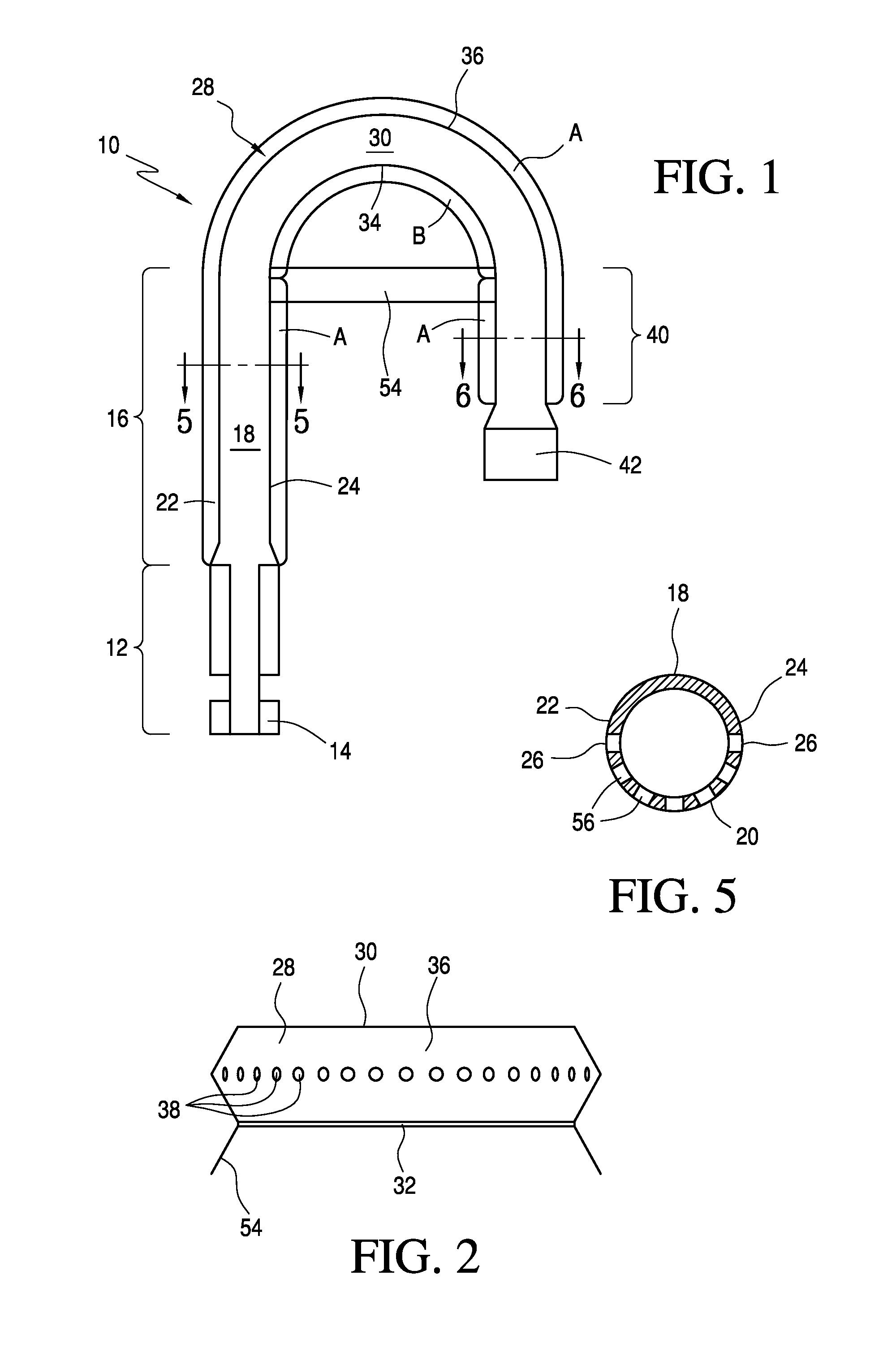
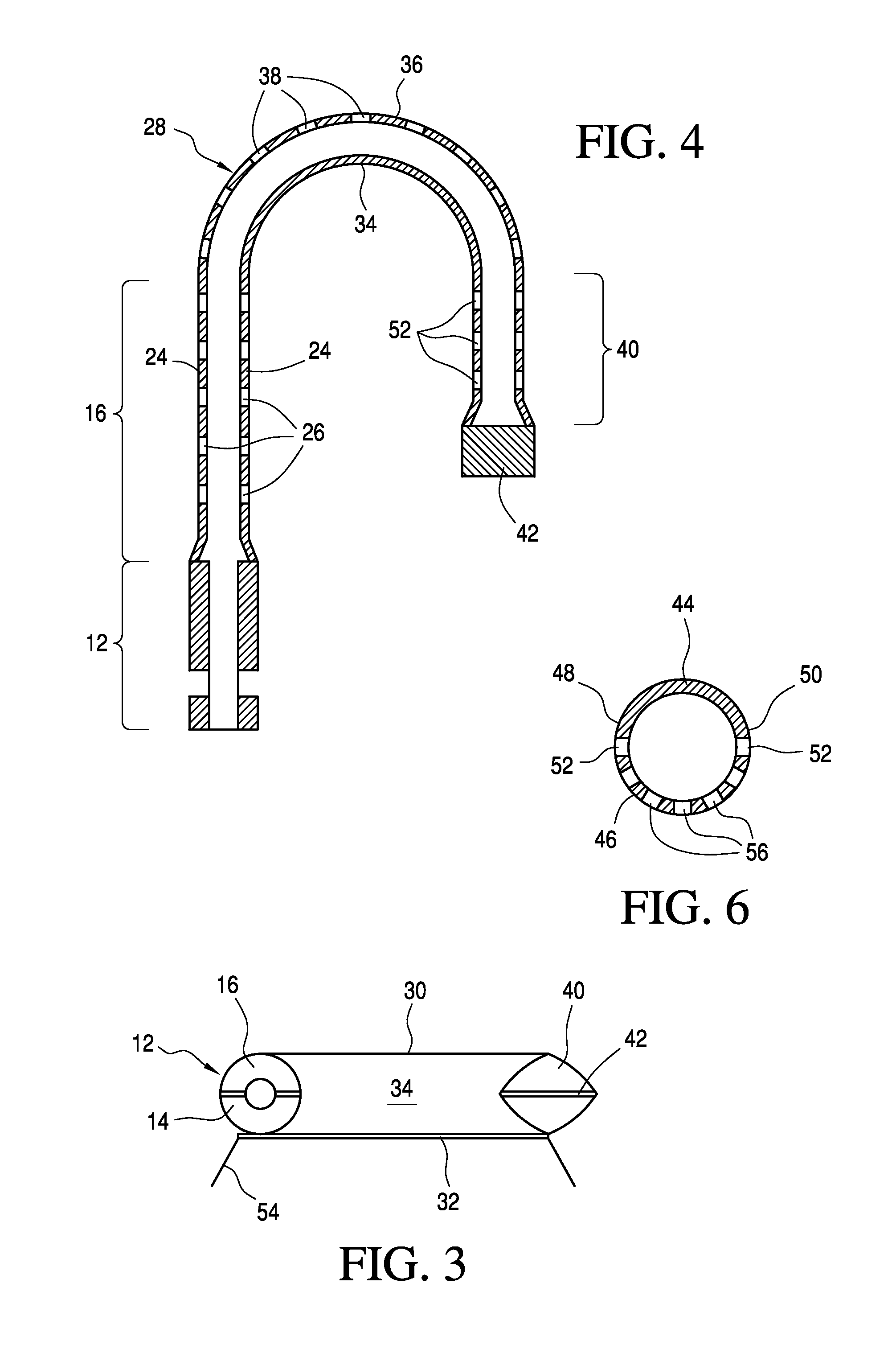
[0005]In order to achieve this object and possibly others, a generally U-shaped burner for a gas grill in accordance with the invention includes a gas inlet section, a first substantially straight section contiguous with the inlet section, preferably having an annular form, a curved section or portion contiguous with the first straight section, also preferably having an annular form, and a second substantially straight section contiguous with the curved section, preferably having an annular form as well. The curved section preferably has a substantially solid upper surface, a substantially solid lower surface, an inner side, and an outer side facing away from the inner side, such that the outer side has a larger radius of curvature than the inner side. The inner side is preferably solid, i.e., unperforated and lacking apertures, and the outer side preferably includes apertures, such that in the curved portion, the only exit apertures for gas being directed from the burner is through the apertures in the outer side of the curved section. In this manner, flame overlap on the inner side of the curved portion of the burner is avoided, while maximum flame coverage area is achieved in other areas surrounding the burner.

Problems solved by technology

However, at the curved portions of the known U-shaped burners, there are no apertures and therefore no flame generation during use.

Method used


Image

  • U-shaped burner for grill
  • U-shaped burner for grill
  • U-shaped burner for grill

Examples


Embodiment Construction

[0016]Referring to the accompanying drawings wherein like reference numerals refer to the same or similar elements, FIG. 1 is a top view of a burner in accordance with the invention which is designated generally as 10. Burner 10 includes a gas inlet section 12 which can be connected to a propane tank or any other suitable fuel source.

[0017]Burner 10 also includes a first substantially straight flame-generating section 16. First straight section 16 has a generally annular cross-section over almost its length whereas, by contrast, inlet portion 12 could have, for example, a pair of flattened portions on either side of a central conduit as illustrated in FIG. 1.

[0018]First straight section 16 preferably includes a substantially solid upper surface 18, a substantially solid lower surface 20, an inner side 24, and an outer side 22 (see FIGS. 1 and 5). The sides 22, 24 are formed from an area at the substantial mid-section or substantial mid-line of the first straight section 16, i.e., at...


PUM


Abstract

Burner for a gas grill includes an inlet section, a first straight section contiguous with the inlet section, a curved section contiguous with the first straight section, and a second straight section contiguous with the curved section and having a portion parallel to the first straight section to provide the burner with a U-shaped configuration. The curved portion has an inner side and an outer side such that the outer side has a larger radius of curvature than the inner side. The inner side of the curved portion preferably lacks apertures, and the outer side of the curved portion preferably includes apertures, such that the only exit apertures for gas being directed from the burner is through the apertures in the outer side.

Description

FIELD OF THE INVENTION[0001]The present invention relates to a burner for a grill, and more specifically, to a U-shaped burner for a grill which enables improved flame generation during use of the burner.BACKGROUND OF THE INVENTION[0002]U-shaped burners for grills are known in the art. One reason for using U-shaped burners is that less tubular stainless steel can be used to manufacture the burner than if the burner were, e.g., straight, while still achieving a high flame coverage area or at least a comparable flame coverage area as a straight burner.[0003]Examples of U-shaped burners include U.S. Pat. No. 1,625,298 (Copilovich), U.S. Pat. No. 3,871,355 (Henry), U.S. Pat. No. 4,112,912 (Ballentine), U.S. Pat. No. 6,314,871 (Holbrook), U.S. Pat. No. 6,389,960 (Williams) and U.S. Pat. No. 6,553,986 (Liu) and U.S. Pub. Pat. Appln. Nos. 2003 / 0205223 (Schlosser), 2004 / 0173200 (Shoeb) and 2005 / 0133018 (Spangrud). Generally, flame apertures are placed on the straight portions of the U-shape...

Claims


Application Information

Patent Timeline
Patent Type & Authority Applications(United States)
IPC IPC(8): F23D14/46F24C3/00A47J37/07
CPCF23D14/58F23D14/105
Inventor KUO, TUNG-SHENG
Owner GEOGLOBAL PARTNERS
Learn More