
Fluid filter system

a filter system and flue gas technology, applied in the field of filters, can solve the problems of reducing the sufficiency of the seal, affecting the operation of one or more engine components,

Active Publication Date: 2009-05-21
DONALDSON CO INC +2
View PDF81 Cites 68 Cited by
  • Summary
  • Abstract
  • Description
  • Claims
  • Application Information

AI Technical Summary

Benefits of technology

[0008]In another aspect, the present disclosure is directed to an apparatus for sealingly connecting a filter medium to a filter system including a base, a container, and an outlet. The endcap includes a body including a substantially ring shaped first wall portion having radial inner portion, a radial outer portion, and a longitudinal axis. The apparatus also includes a first seal member configured to establish a first radially facing seal interface with respect to a first radially facing surface associated with the outlet and having at least a portion thereof disposed a first axial distance from the filter medium. The apparatus also includes a second seal member configured to establish a radially facing seal interface with respect to a second radially facing surface associated with the base and bei...

Problems solved by technology

Unfiltered and / or priming fluid downstream of the filter medium, either from insufficient sealing and / or from operator priming, may result in damage to one or more engine components during operation.
The '140 patent may, however, require numerous components to achieve these seals, complicating the assembly and alignment that may require precise manufacturing tolerances thereof and / or potential reduce the sufficiency of the seal.

Method used


Image

  • Fluid filter system
  • Fluid filter system
  • Fluid filter system

Examples


Embodiment Construction

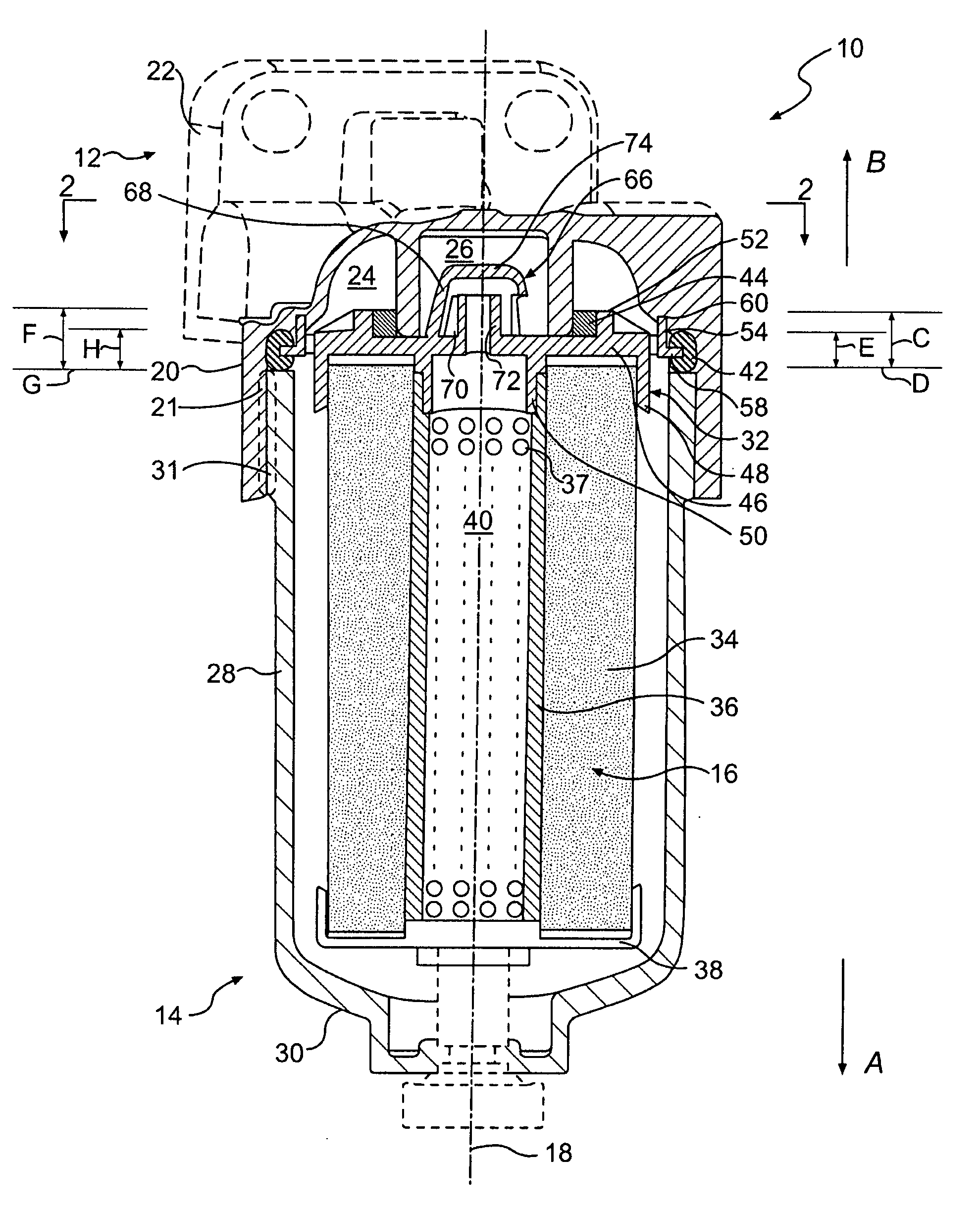
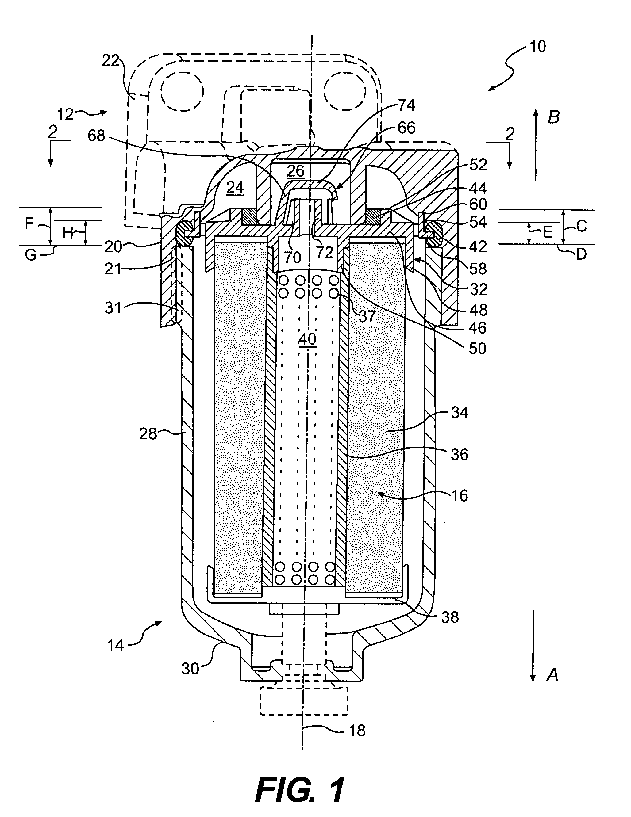
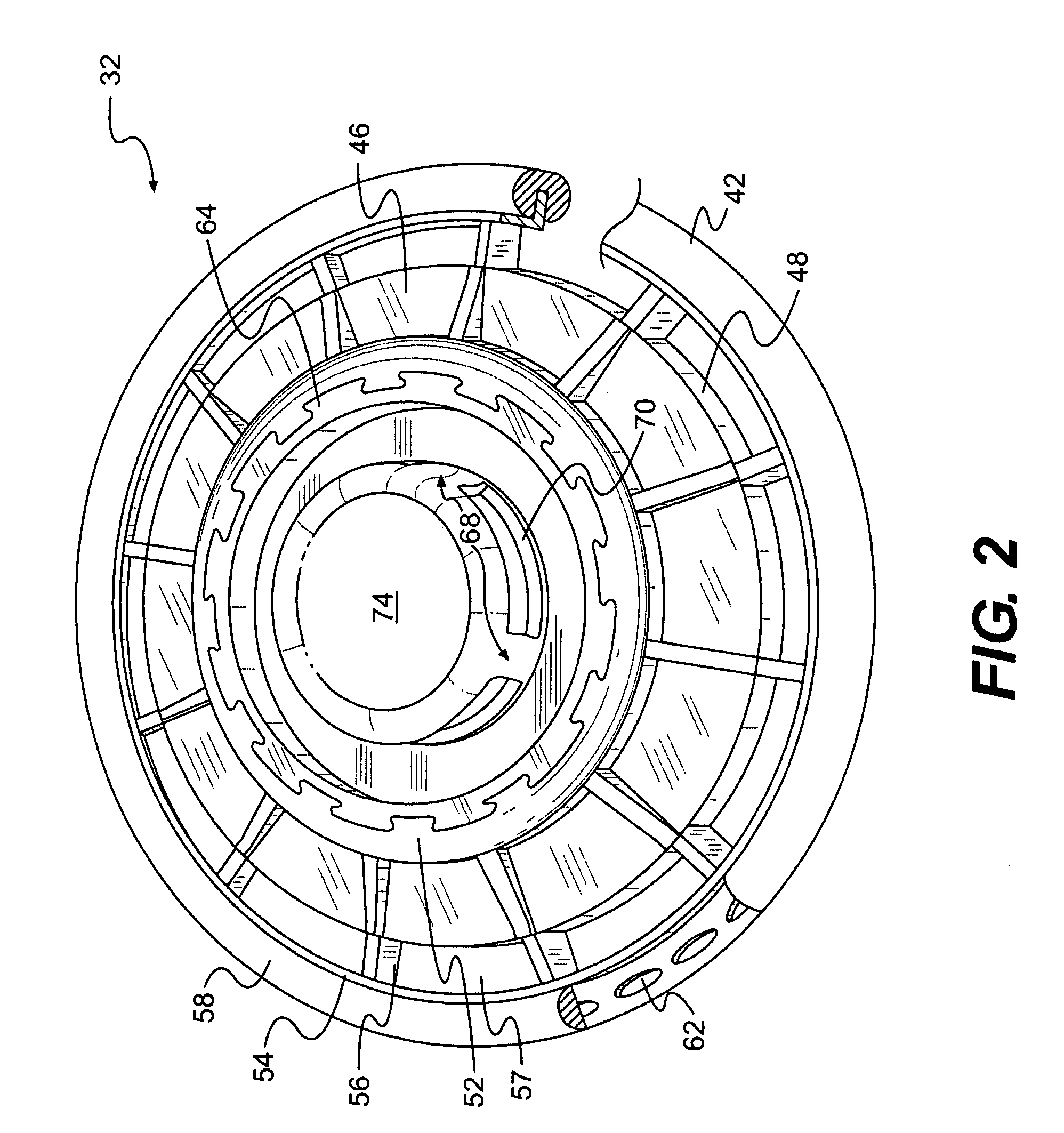
[0013]FIG. 1 illustrates an exemplary fluid filter system 10. Fluid filter system 10 may include a base 12, a container 14, a filter assembly 16, and a longitudinal axis 18. Filter system 10 may be one of several components within a fluid system (not shown) and may be configured to receive unfiltered fluid from one or more upstream components of the fluid system, trap particles suspended within the unfiltered fluid, i.e., filter the fluid, and provide filtered fluid to one or more downstream components of the fluid system. The fluid system may include any type of fluid system, e.g., a fuel delivery system, a lubricating system, and / or a coolant system, and may or may not be operatively associated with an engine (not shown). Additionally, fluid filter system 10 may be configured to filter any type of fluid, such as, for example, gasoline, diesel fuel, lubricating oil, water, coolant, and / or any other type of fluid. It is contemplated that the fluid of the fluid system may or may not ...


PUM

PropertyMeasurementUnit
Flow rateaaaaaaaaaa
Shapeaaaaaaaaaa
Distanceaaaaaaaaaa

Abstract

An endcap including a first plate member including a radial inner portion, a radial outer portion, and defining a longitudinal axis. The endcap also includes a flange disposed between the radial inner and outer portions of the first plate member and projecting axially along the longitudinal axis in a first direction. The endcap also includes a first seal member disposed adjacent the flange. The first seal includes a first portion thereof engaged with an axial facing surface of the first plate member and a second portion thereof engaged with a radially facing surface of the flange. The endcap further includes a second plate member disposed radially outward of the radial outer portion and a second seal member disposed adjacent the second plate member including at least a portion thereof axially spaced from the axially facing surface of the first plate member in a second direction along the longitudinal axis opposite the first direction.

Description

TECHNICAL FIELD [0001]The present disclosure relates to filters and, more particularly, to fluid filter systems.BACKGROUND [0002]Cartridge style fluid filters, such as, for example, fuel or lubricant filters associated with an engine, typically include a replaceable filter element contained within a canister that is threadingly engaged to the engine. Unfiltered fluid, e.g., fuel or lubricant, is received by the filter via an inlet port, particulates are removed from the unfiltered fluid via the filter element, and filtered fluid is delivered to the engine via an outlet port. The filter element often includes a generally cylindrical filter medium, e.g., fabric or other porous material, supported within the canister via one or more endcaps, such that unfiltered fluid flows through the filter medium in a generally radial direction. An endcap typically supports and / or positions the filter medium within the canister and with respect to the inlet and outlet ports. Fluid filters usually al...

Claims


Application Information

Patent Timeline
IPC IPC(8): B01D35/30B01D61/14
CPCB01D29/21B01D35/30B01D27/106B01D2201/304B01D2201/34B01D2201/295
Inventor SALVADOR, CHRISTOPHER J.HEIBENTHAL, RANDALL W.DEEDRICH, DENNIS M.HARDER, DAVID B.HACKER, JOHN R.EISENMENGER, RICHARD
Owner DONALDSON CO INC
Learn More