Systems and methods for computational design and modeling of buildings

a technology of systems and methods, applied in the field of computational design and modeling, can solve the problems of limited functionality of software packages and designed for a single purpos

Inactive Publication Date: 2009-05-21
MIC IND INC
View PDF18 Cites 33 Cited by
  • Summary
  • Abstract
  • Description
  • Claims
  • Application Information

AI Technical Summary

Benefits of technology

[0005]It is an object of the present invention to provide systems and methods that can accept minimal information (e.g., data such as building width, length, total height, wall height, and selectable building shape) and generate a three-dimensional design of the desired building. The model may be a comprehensive three-dimensional design which can be rotated, edited, and rendered and may include details relating to structural features of building panels (e.g., sheet metal thickness and yield strength), foundation designs, flooring, windows and doors, for example. The systems and methods may also provide suitable views, schedules and engineering documents for approval for the building design.
[0006]According to an exemplary embodiment, a computer-assisted method is described for automatically generating a design for a building that comprises structurally supportive building panels of sheet material, at least some of said building panels including curved sections, and for generating a three-dimensional image of said design. The method comprises: receiving first building information via a first graphical user interface of a computer, said first building information comprising a length, a width, a total height and a wall height of a building to be designed; determining whether said length, said width, said total height, said wall height, and a selectable building shape comprising at least one curved portion yield a valid set of building parameters, said selectable building shape being either computer-specified or user-specified; if the set of building parameters is valid, generating with a first software module at said computer a design of said building, wherein said first software module is configured to generate said design of said building, including wall portions and a roof portion, using minimum information consisting of said length, said width, said total height, said wall height, and said selectable building shape; generating a first image of said design; performing a structural analysis of said design; determining whether said structural analysis satisfies one or more requirements; communicating said length, said width, said total height, said wall height, and said selectable building shape to a second software module at said computer; generating a second three-dimensional image of said building using said second software module, the second three-dimensional image being different from the first image; and displaying said second three-dimensional image at a second graphical user interface at said computer, said second user interface configured to permit a user to modify said three-dimensional image to include one

Problems solved by technology

Such software packages are generally limited in functionality and designed for a single purpose, and build

Method used


Image

  • Systems and methods for computational design and modeling of buildings
  • Systems and methods for computational design and modeling of buildings
  • Systems and methods for computational design and modeling of buildings

Examples


Embodiment Construction

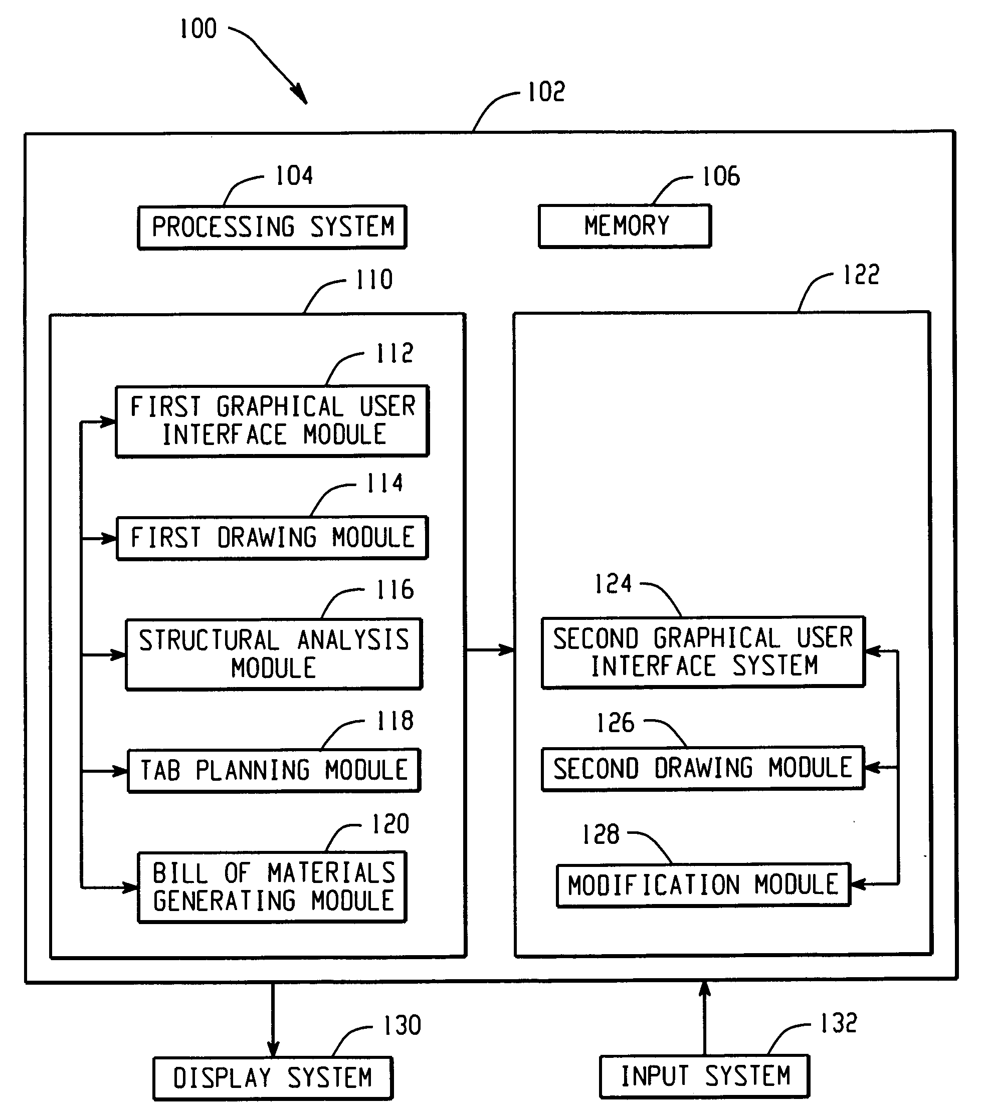
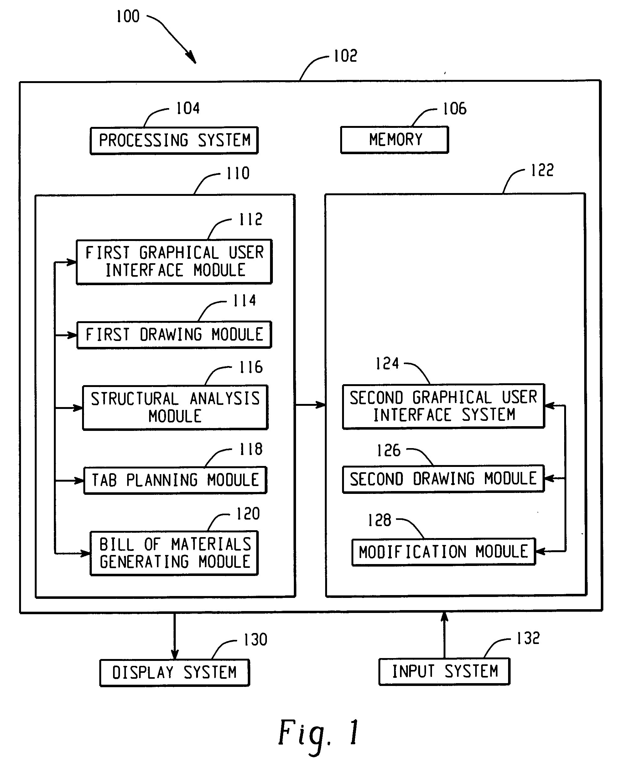
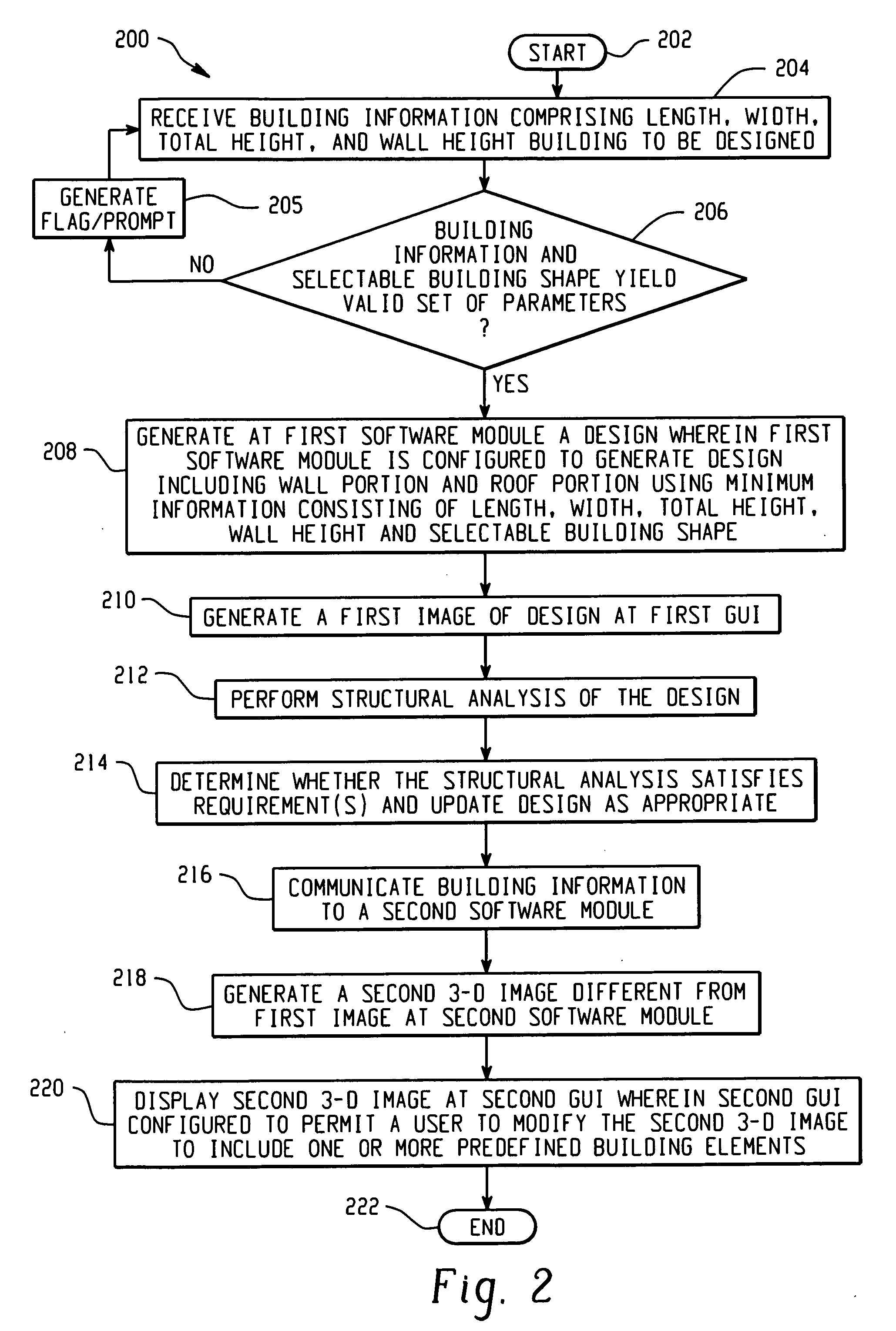
[0025]Exemplary methods and systems are described herein for designing buildings that comprise structurally supportive building panels of sheet material (e.g., galvanized steel sheet or other types of sheet metals) and that possess roofs having at least some curved sections. Such buildings generally have self-supporting wall and roof structures and may be referred to as clear-span buildings insofar as they do not require structural support posts and beams that might otherwise obstruct useable interior space. Typical shapes for such buildings may include, for example, those with circularly shaped roof portions with or without straight side walls (e.g., the curved roof portion may extend to the building foundation or may be supported by straight, vertical side walls), those with double-radius style roof portions wherein a central portion of the roof possesses one radius of curvature and wherein curved portions of the roof near side walls of the building possess another radius of curva...


PUM


Abstract

A method and system generates a building design and a three-dimensional image thereof. First building information comprising a length, width, total height and wall height of a building is received via a first graphical user interface. If the length, width, total height, wall height, and a selectable building shape yield a valid set of building parameters, a design of said building is generated at a first software module, which is configured to generate the design, including wall portions and a roof portion, using minimum information consisting of the length, width, total height, wall height, and selectable building shape. A first image and a structural analysis of the design are generated. A second software module generates a second three-dimensional image of the building, which is different from the first image. A second graphical user interface permits a user to modify the second image to include predefined building elements.

Description

CROSS-REFERENCE TO RELATED APPLICATIONS[0001]This application claims priority to U.S. Provisional Patent application entitled “Method and System for Computation and Modeling Specialized Metal Buildings” (Attorney Docket No. 011925-0066-888) filed on Nov. 16, 2007, the entire contents of which are incorporated herein by reference.FIELD OF THE DISCLOSURE[0002]This disclosure relates to computational design and modeling, and more particularly to systems and methods for computational design and modeling of buildings.BACKGROUND INFORMATION[0003]Presently, there are software packages that facilitate building design in the construction industry. Such software packages can produce architectural renderings or perform a structural analysis or generate two-dimensional drawings. Such software packages are generally limited in functionality and designed for a single purpose, and building designers often need to purchase multiple software packages for each of the different stages of design. Indiv...

Claims


Application Information

Patent Timeline
IPC IPC(8): G06T17/00
CPCG06F2217/42G06F17/5004G06F30/13G06F2113/24
Inventor MORELLO, FREDERICKMARCH, CHRISTOPHER RYANCANTRELL, CLIFFORD B.
Owner MIC IND INC
Why Eureka
Try Eureka