
Apparatus and method of reducing banding artifact visibility in a scanning apparatus

Active Publication Date: 2009-05-21
HEWLETT PACKARD DEV CO LP
View PDF8 Cites 4 Cited by
  • Summary
  • Abstract
  • Description
  • Claims
  • Application Information

AI Technical Summary

Benefits of technology

[0006]According to an aspect of the invention there is provided a method of reducing the visibility of primary banding artifacts on a printed document produced by a printer, the method comprising causing the printer to print synthetic secondary banding artifacts so that the combined spatial frequency of primary banding artifacts and synthetic secondary banding artifacts on the printed document is greater than the spatial frequency of the primary banding artifacts on the printed document.
[0009]According to a further aspect of the invention there is provided a method of reducing the visibility of artifacts caused by differential scan bow in a scanning instrument, the scanning instrument arranged to produce a plurality of adjacent swaths of scan lines, wherein the method comprises controlling the scanning instrument to produce a swath of scan lines such that an outer scan line of the swath overlaps with an outer line of an adjacent swath of scan lines.

Problems solved by technology

The scan lines and scan line spacing can suffer from a number of errors which may be caused by the optical system used to produce the scan lines on the photosensitive medium, for example due to an aberration such as distortion in the optical system.
Errors in the scan lines produced on the photoconductor can produce visible artifacts in the printed image on the print medium, which are undesirable.
Artifacts resulting from scan line errors may be detrimental to the performance of the electrical circuit that is produced.

Method used


Image

  • Apparatus and method of reducing banding artifact visibility in a scanning apparatus
  • Apparatus and method of reducing banding artifact visibility in a scanning apparatus
  • Apparatus and method of reducing banding artifact visibility in a scanning apparatus

Examples


Embodiment Construction

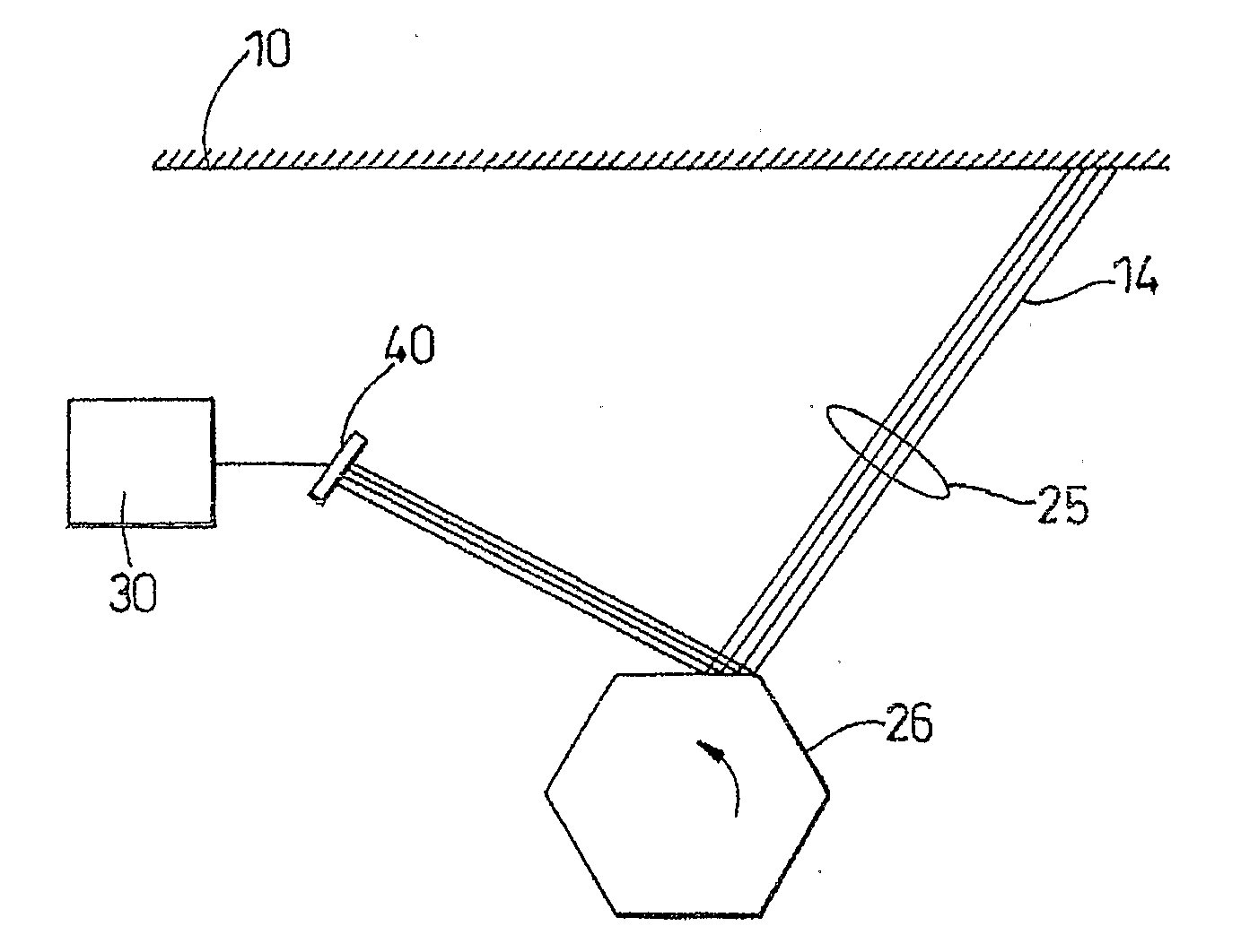
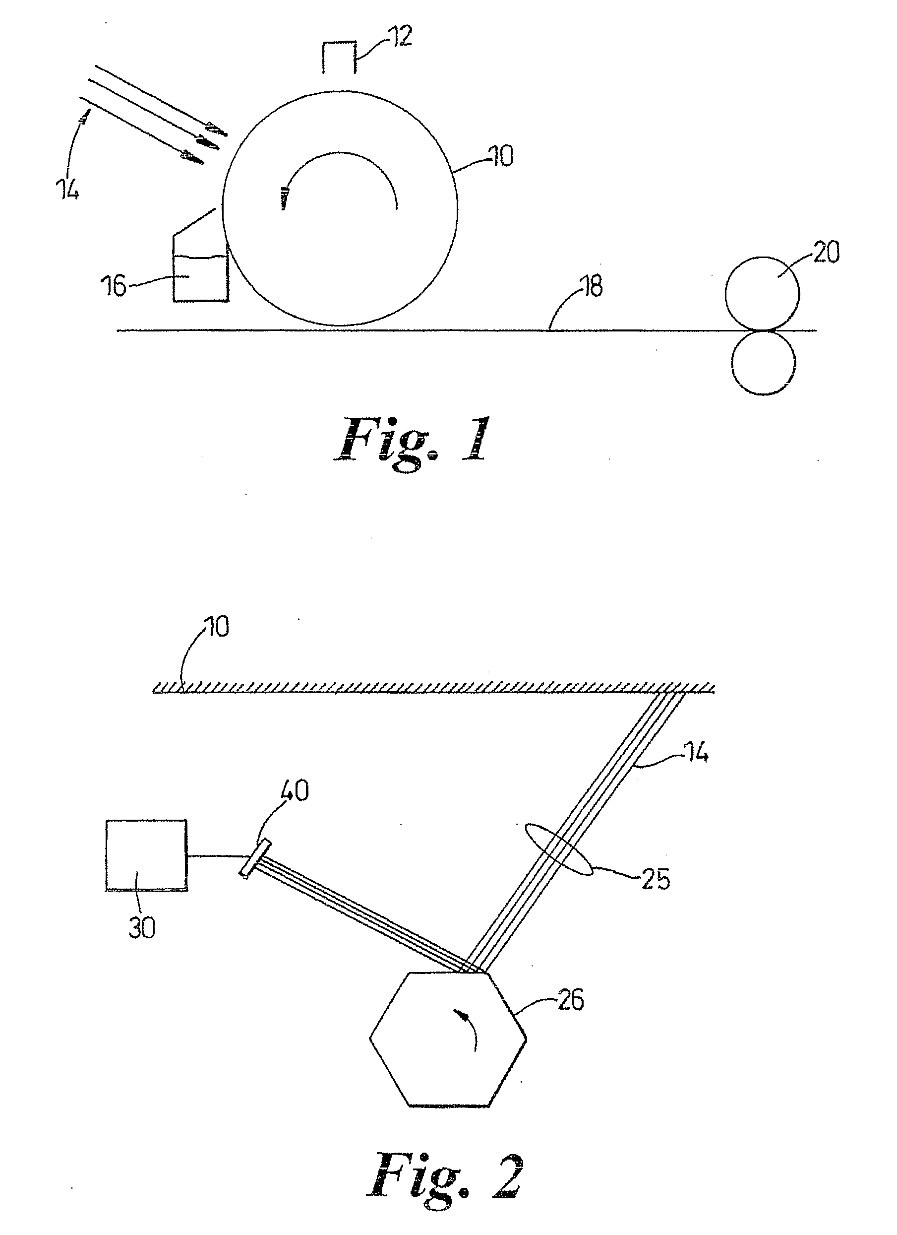
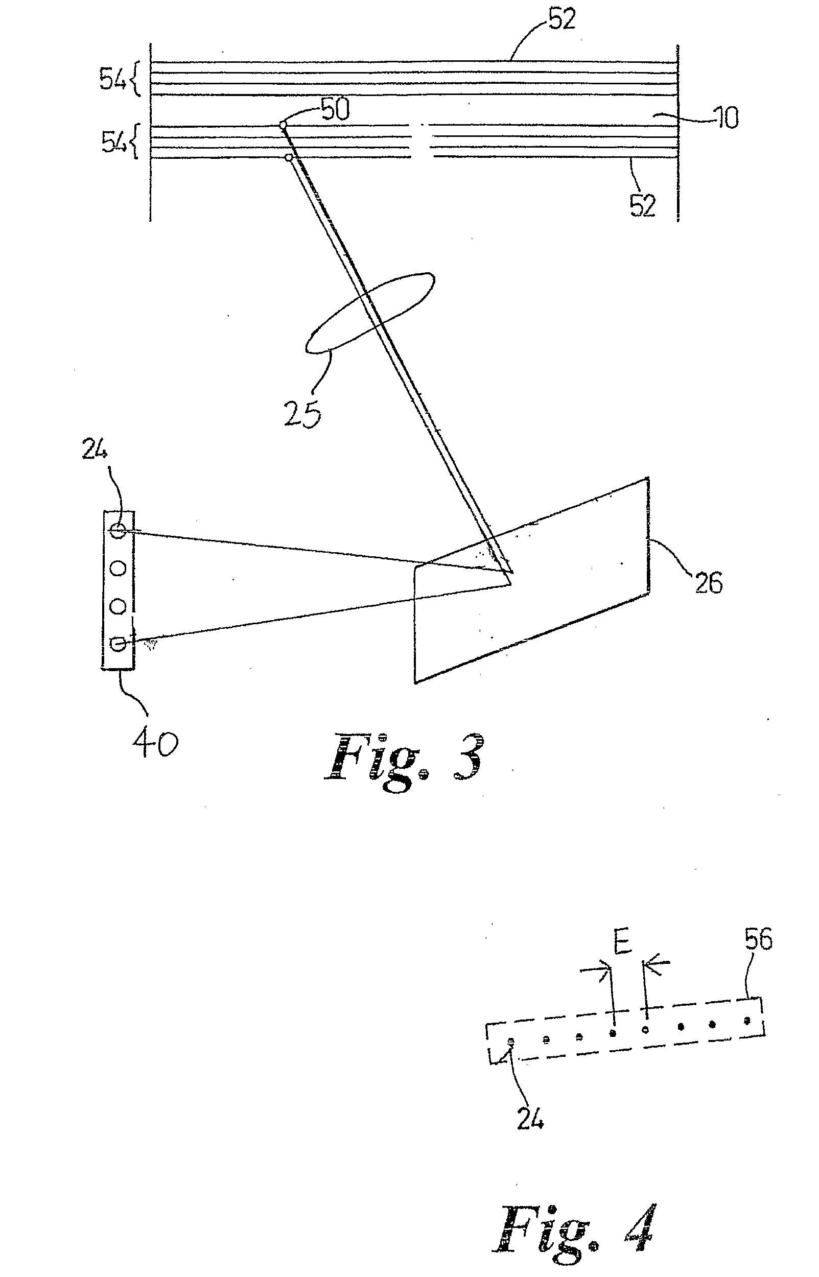
[0028]Referring to FIG. 1, a printer comprises a photoconductor 10 that generally forms the outer surface of a rotatable cylindrical drum. During the printing process the surface of the photoconductor 10 is uniformly charged with static electricity by, for example, a corona discharge 12. Portions of the photoconductor 10 are exposed with light 14 from an array of light sources 40 (illustrated in FIGS. 2 and 3). The drum is rotated so that the image to be printed is formed on the photoconductor 10. The light 14 discharges the charge on the drum in exposed areas and leaves a charged latent image. The latent image is then developed by applying a toner 16, such as a liquid ink toner (e.g. as in LEP printing) or a pigmented dry powder toner, over the surface of the photoconductor 10. The toner 16 adheres to the discharged areas of the photoconductor 10 so that the latent image becomes visible. The toner 16 is then transferred from the photoconductor 10 to a sheet of paper 18 or to some o...


PUM


Abstract

A method of, and apparatus for, reducing the visibility of banding artifacts on a printed medium comprising producing synthetic artifacts on the printed medium, overlapping scan lines at swath boundaries and controlling exposure along a scan line to reduce the visibility of the banding artifacts.

Description

BACKGROUND OF THE INVENTION[0001]Laser printers, digital printing presses, copiers, fax machines, plate setters, direct-to-film laser printers, scanned laser displays, other printing and display devices and some systems used for the fabrication of electrical circuits, use a plurality of light sources to emit light that is scanned across a medium. The light produces a number of exposed scan lines on the medium where the medium has been altered by the light to form a latent image. The scan lines and scan line spacing can suffer from a number of errors which may be caused by the optical system used to produce the scan lines on the photosensitive medium, for example due to an aberration such as distortion in the optical system.[0002]Dry toner laser printers, and liquid electrophotographic (LEP) laser printers (to name only some printers) generally use a discharge area development (DAD) electrophotographic process in which light is used to selectively discharge electrical charge on a pho...

Claims


Application Information

Patent Timeline
IPC IPC(8): B41J2/47
CPCH04N1/1135H04N1/1911H04N1/12
Inventor PLOTKIN, MICHAELKELLA, DRORTOWNER, DAVIDFISCHER, MANI
Owner HEWLETT PACKARD DEV CO LP
Learn More