Computed tomography method and system

a computed tomography and image technology, applied in tomography, applications, instruments, etc., can solve the problems of inefficient and slow conventional method of generating and displaying images of multiple types, image acquisition with polychromatic x-ray beam suffer from beam hardening artifacts,

Inactive Publication Date: 2009-05-21
GENERAL ELECTRIC CO
View PDF17 Cites 30 Cited by
  • Summary
  • Abstract
  • Description
  • Claims
  • Application Information

AI Technical Summary

Problems solved by technology

Due to this relationship, images acquired with a polychromatic x-ray beam suffer from beam hardening artifacts as is well known by those skilled in the art.
The problem is that the conventional method of generating and displaying images of multiple types is slow and inefficient.

Method used


Image

  • Computed tomography method and system
  • Computed tomography method and system
  • Computed tomography method and system

Examples


Embodiment Construction

[0016]In the following detailed description, reference is made to the accompanying drawings that form a part hereof, and in which is shown by way of illustration specific embodiments that may be practiced. These embodiments are described in sufficient detail to enable those skilled in the art to practice the embodiments, and it is to be understood that other embodiments may be utilized and that logical, mechanical, electrical and other changes may be made without departing from the scope of the embodiments. The following detailed description is, therefore, not to be taken as limiting the scope of the invention.

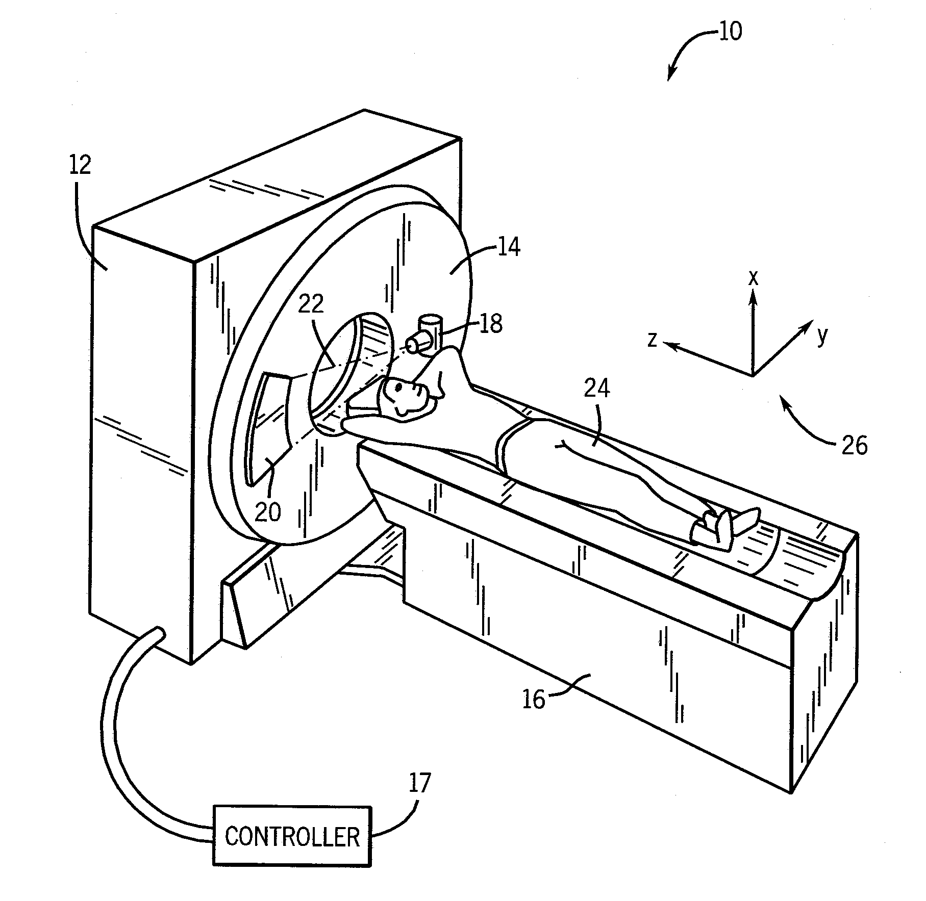
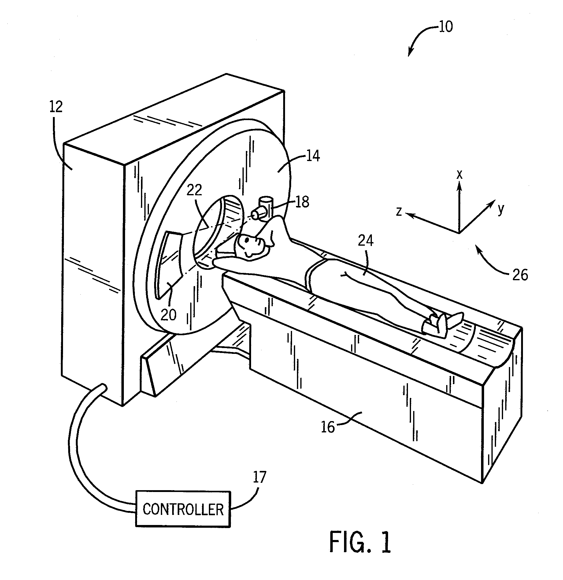
[0017]Referring to FIG. 1, a schematic representation of a computed tomography (CT) system 10 according to an embodiment is shown. The CT system 10 includes a gantry 12, a rotatable gantry portion 14, a support 16, and a controller 17. The rotatable gantry portion 14 is adapted to retain an x-ray source 18 and a detector assembly 20. The x-ray source 18 is configured to emit a...


PUM


Abstract

A method of diagnostic imaging is disclosed herein. The method includes acquiring CT projection data at a first x-ray energy level and a second x-ray energy level. The method includes reconstructing a first image pair using a basis material decomposition algorithm and the CT projection data. The method includes displaying a first image from the first image pair. The method includes transforming the first image pair into a second image using image data from the first image pair. The method also includes displaying a second image. A CT system is also disclosed.

Description

BACKGROUND OF THE INVENTION[0001]The subject matter disclosed herein relates to a computed tomography method and system.[0002]Typically, in computed tomography (CT) imaging systems, an x-ray source emits a fan-shaped or a cone-shaped x-ray beam toward a subject or object, such as a patient or a piece of luggage, positioned on a support. The beam, after being attenuated by the subject, impinges upon a detector assembly. The intensity of the attenuated x-ray beam received at the detector assembly is typically dependent upon the attenuation of the x-ray beam by the subject.[0003]In known third generation CT systems, the x-ray source and the detector assembly are rotated on a rotatable gantry portion around the object to be imaged so that a gantry angle at which the fan-shaped x-ray beam intersects the object constantly changes. The detector assembly is typically made of a plurality of detector modules. Data representing the intensity of the received x-ray beam at each of the detector e...

Claims


Application Information

Patent Timeline
Patent Type & Authority Applications(United States)
IPC IPC(8): A61B6/03
CPCA61B6/032A61B6/482A61B6/463
Inventor LICATO, PAUL E.THOMSEN, BRIANLEVERENTZ, JAYNNEMUDRIK, BORISGAUTHAM, SARDAR MALGABRIELSE, BRADLEYSORKIN, YAN
Owner GENERAL ELECTRIC CO
Why Eureka
Try Eureka