
Method and apparatus to decode audio matrix

a technology of audio matrix and decoding method, which is applied in the field of audio reproduction system, can solve the problems of not being able to precisely achieve the localization of a sound image in a space, sound source generated and not being able to achieve the localization of a sound image clearly in a multichannel environmen

Inactive Publication Date: 2009-05-21
SAMSUNG ELECTRONICS CO LTD
View PDF15 Cites 19 Cited by
  • Summary
  • Abstract
  • Description
  • Claims
  • Application Information

AI Technical Summary

Benefits of technology

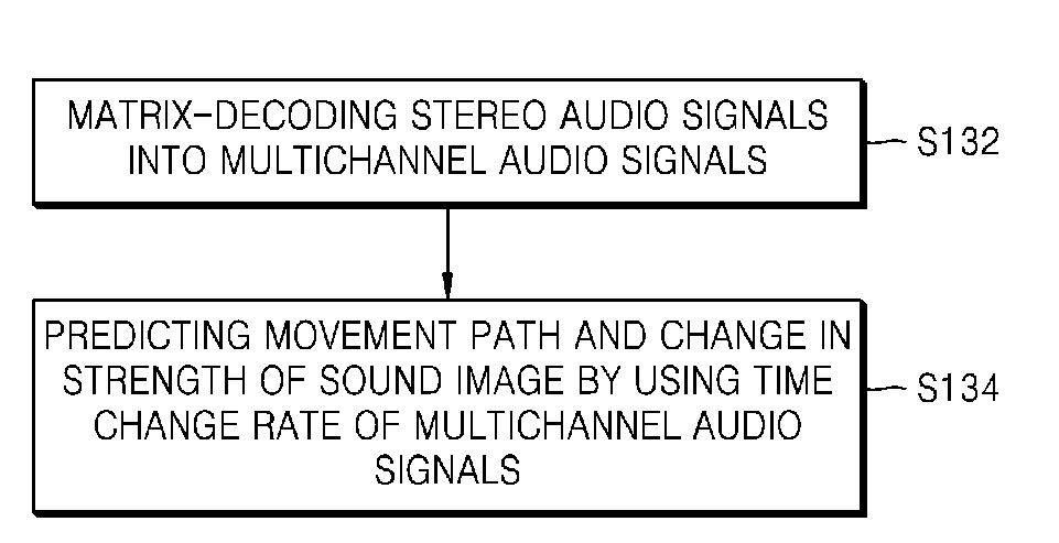
[0015]The foregoing and/or other aspects and utilities of the general inventive concept may also be achieved by providing an apparatus to decode audio matrix, the apparatus including a matrix decoder to matrix-decode stereo audio signals into multichannel audio signals, virtual sound source movement tracking unit to predict a movement path and a change in strength of a sound image by using a time change rate of the multichannel audio signals, and a channel power distributor to redistribute powers to positions of channel speakers in a multichannel arrangement based on the movement path and the change in strength of a sound image predicted by the virtual sound source movement tracking unit.
[0016]The foregoing and/or other aspects and utilities of the general inventive concept may also be achieved by providing an audio matrix decoding

Problems solved by technology

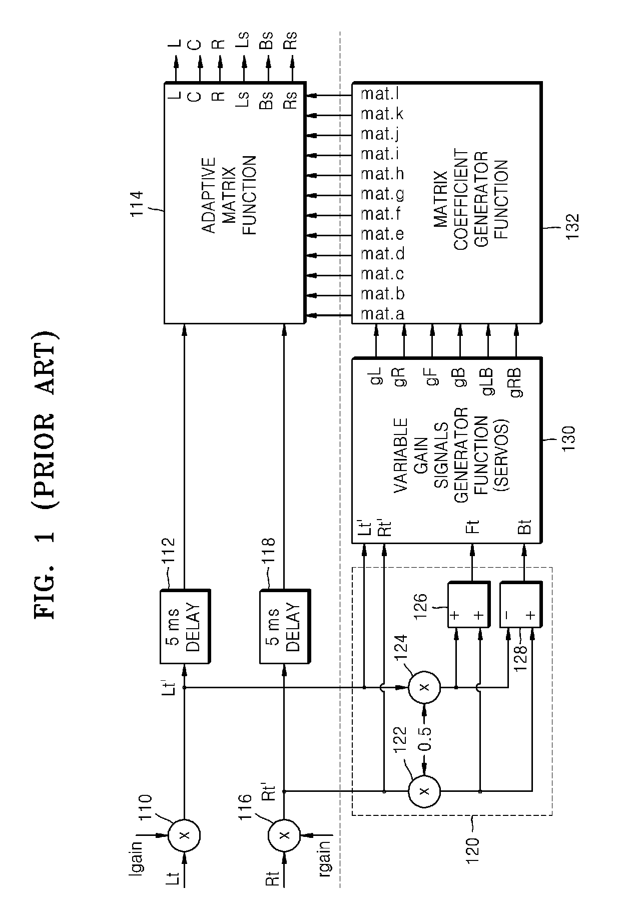
Thus, signals of channels output to a conventional passive matrix decoder have low separation between channels so that localization of a sound image is not clearly achieved in a multichannel environment.
However, in a conventional matrix decoding system illustrated in FIG. 1, a position of a virtual sound source generated in a multichannel environment is not considered.
Thus, localization of a sound image is not precisely achieved in a space.
Furthermore, precisely representing a change in positions of a sound source moving in a virtual space is not easily accomplished.
Thus, a capability of dynamically expressing a sound image is insufficient.
That is, the conventional matrix decoding system is not capable of restoring a sound image moving between channels so as to restore surround sound and a sound image that exists in a rear channel (a surround channel).

Method used


Image

  • Method and apparatus to decode audio matrix
  • Method and apparatus to decode audio matrix
  • Method and apparatus to decode audio matrix

Examples


Embodiment Construction

[0032]The present general inventive concept will now be described more fully with reference to the accompanying drawings, in which exemplary embodiments of the general inventive concept are illustrated.

[0033]Reference will now be made in detail to embodiments of the present general inventive concept, examples of which are illustrated in the accompanying drawings, wherein like reference numerals refer to the like elements throughout. The embodiments are described below in order to explain the present general inventive concept by referring to the figures.

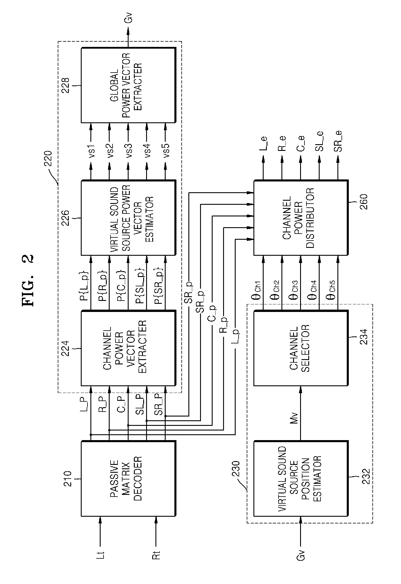
[0034]FIG. 2 illustrates an apparatus for audio matrix decoding according to an embodiment of the present general inventive concept. Referring to FIG. 2, the apparatus for audio matrix decoding includes a passive matrix decoder 210, a virtual sound source extractor 220, a virtual sound source movement tracking unit 230, and a channel power distributor 260.

[0035]Furthermore, the virtual sound source extractor 220 includes a channel pow...


PUM


Abstract

A method of audio matrix decoding in which a moving sound image is restored includes decoding multichannel signals from stereo signals, extracting strengths and positions of virtual sound sources existing between channels based on power vectors of the decoded multichannel signals, comparing the strengths and positions of the extracted previous and current virtual sound sources to predict position movement and the strengths of the virtual sound sources, and redistributing powers to positions of channel speakers in a multichannel arrangement based on the predicted position of a sound image.

Description

CROSS-REFERENCE TO RELATED APPLICATIONS[0001]This application claims priority under 35 U.S.C. §119(a) from Korean Patent Application No. 10-2007-0116771, filed on Nov. 15, 2007, in the Korean Intellectual Property Office, the disclosure of which is incorporated herein in its entirety by reference.BACKGROUND OF THE INVENTION[0002]1. Field of the Invention[0003]The present general inventive concept relates to an audio reproduction system, and more particularly, to a method and apparatus to decode audio matrix in which a moving sound image is restored by using an audio reproducing device such as a digital television (DTV) or audio-video (AV) receiver.[0004]2. Description of the Related Art[0005]Traditionally, when a user wanted to see a movie or the like at home, the user could see, for example, a movie through ground wave broadcasting from a television broadcast, etc. However, recently, the user can listen to an original sound of a movie, etc., due to the spread of video tapes, video ...

Claims


Application Information

Patent Timeline
IPC IPC(8): H04R5/00
CPCH04S1/007H04S3/008H04S2420/07H04S5/005H04S2400/11H04S3/02G10L19/008G11B20/10
Inventor CHO, SUNG-HO
Owner SAMSUNG ELECTRONICS CO LTD
Learn More