Radio communication apparatus and radio communication method

a radio communication and radio communication technology, applied in the field of radio communication apparatus and radio communication method, can solve the problem of increasing distance and increasing the effect of transmission distan

Active Publication Date: 2009-05-21
PANASONIC INTELLECTUAL PROPERTY CORP OF AMERICA
View PDF0 Cites 10 Cited by
  • Summary
  • Abstract
  • Description
  • Claims
  • Application Information

AI Technical Summary

Benefits of technology

[0008]The present invention provides an advantage of obtaining diversity effect in cooperative relay adopting space time encoding even when there is an error in a signal received by a relay station.

Problems solved by technology

However, when a high-frequency radio band is used, although a high transmission rate can be expected in a short distance, attenuation due to transmission distance becomes greater as the distance increases.

Method used


Image

  • Radio communication apparatus and radio communication method
  • Radio communication apparatus and radio communication method
  • Radio communication apparatus and radio communication method

Examples


embodiment 1

[0037]According to the present embodiment, when there are no errors in S1 and S2, relay station 1 encodes S1 and S2 by encoding generating the signal sequence (the first row of matrix A) that is different from the signal sequence (the second row of matrix A) used in relay station 2. On the other hand, when there is an error in either S1 or S2, relay station 1 encodes only the signal without an error by encoding generating the signal sequence (the second row of matrix A). Moreover, relay station 1 cancels relay transmission of a signal with an error.

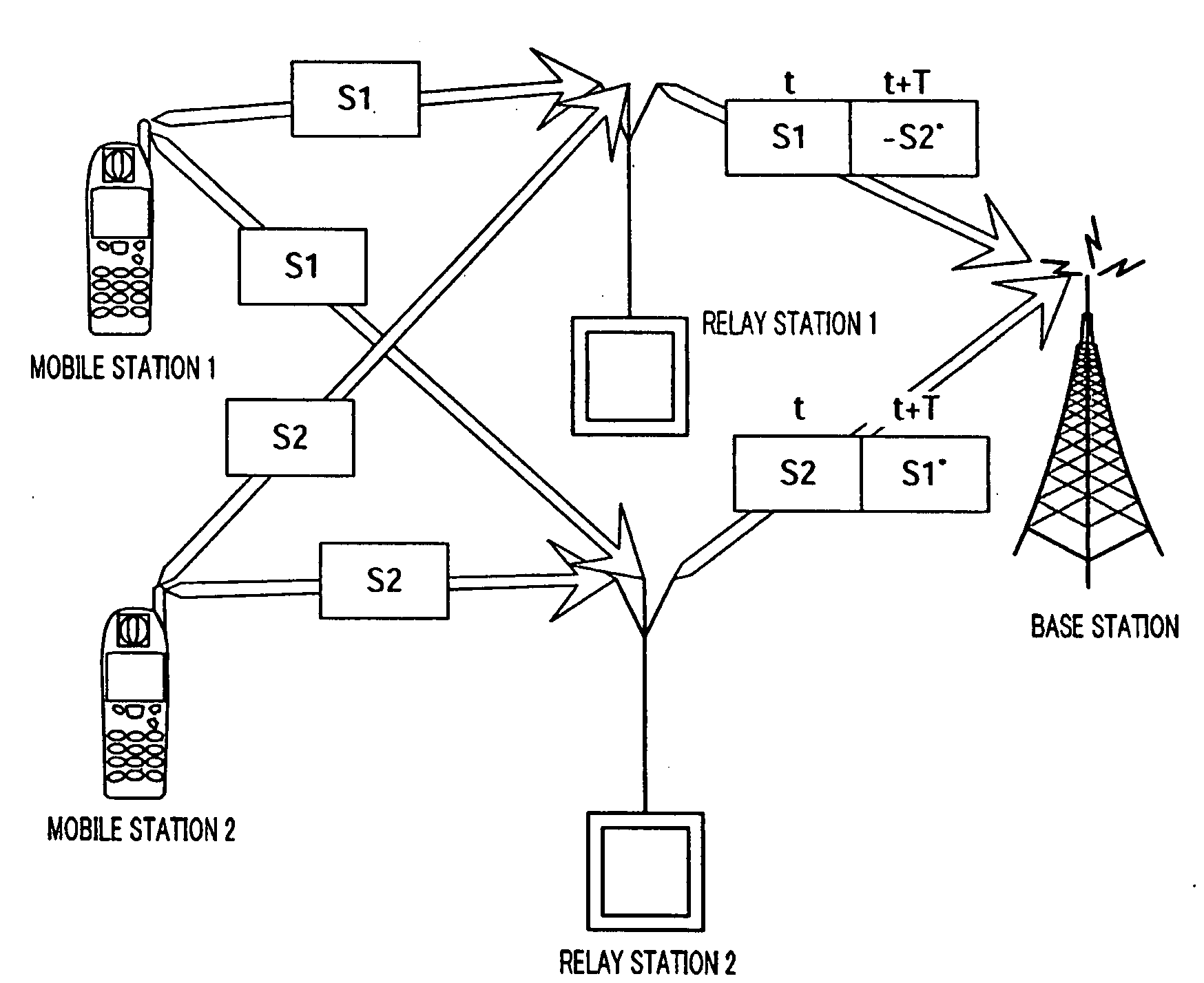
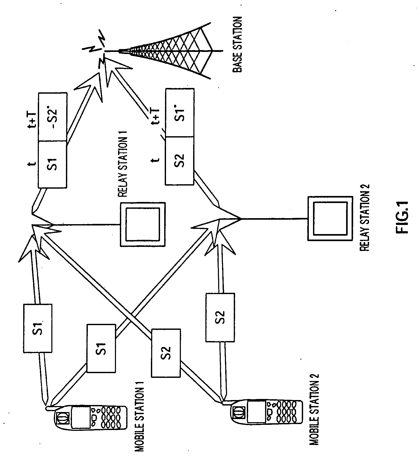
[0038]When there are no errors in S1 and S2, relay station 1 encodes S1 and S2 and generates the first row of matrix A as explained above, and relays S1 at t and −S2* at t+T to the base station.

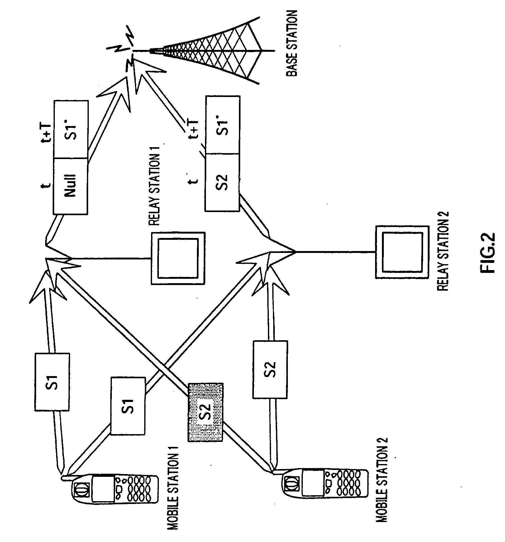
[0039]On the other hand, as shown in FIG. 2, when there is no error in S1 and there is an error in S2, relay station 1 cancels relay transmission of S2 and encodes S1 alone and generates the second row of matrix A. Accordingly, relay station 1 does...

embodiment 2

[0074]The present embodiment is different from Embodiment 1 in that, when there is an error in either S1 or S2, relay station 1 receives from relay station 2 a signal relayed by relay station 2 and prepares for a retransmission request from the base station. By this means, relay station 1 can receive the same signal as a signal not transmitted by relay station 1 due to errors, so that relay station 1 can relay a signal received from relay station 2 to the base station when the base station requests a retransmission.

[0075]For example, as shown in FIG. 8, when there is no error in S1 and there is an error in S2, relay station 1 receives S2 that relay station 2 relays to the base station at time t when relay station 1 does not relay. Moreover, when there is no error in S2 received from relay station 2, relay station 1 stores S2 in a buffer. Then, relay station 1 transmits S2 stored in the buffer to the base station upon receiving are transmission request from the base station. The rest...

embodiment 3

[0085]The present embodiment is different from Embodiment 1 in assigning different priorities to relay stations 1 and 2, so that, when there is no error in the signal scheduled to be transmitted at time t and there is an error in the signal scheduled to be transmitted at time t+T, the relay station of the lower priority checks whether or not the relay station of the higher priority performs relay transmission at time t and then performs relay transmission. By this means, when there are errors in signals from different mobile stations in relay stations 1 and 2, it is possible to prevent relay stations 1 and 2 from transmitting different signals at t+T.

[0086]For example, if the priority of relay station 1 is high and the priority of relay station 2 is low, as shown in FIG. 11, when there is no error in S2 scheduled to be transmitted at time t and there is an error in S1 scheduled to be transmitted at time t+T, relay station 2 receives the signal from relay station 1 at time t and chec...


PUM


Abstract

Provided is a mobile communication system capable of obtaining a diversity effect even when a signal received by a relay station has an error in a corporate relay to which time space encoding is applied. In this mobile communication system, when S1 has no error and S2 has an error, a relay station (1) does not perform relay transmission at time t (Null) and relay-transmits S1* to a base station at time t+T. That is, in this case, the relay station (1) relay-transmits at time t+T only S1 to be transmitted at time t when no error is contained in either S1 or S2. Moreover, when S1 has an error and S2 has no error, the relay station (1) relay-transmits S2 at time t and does not perform relay transmission at time t+T (Null). That is, in this case, the relay station (1) relay-transmits only S2 to be transmitted at time t+T at time t if no error is contained in either S1 or S2.

Description

TECHNICAL FIELD[0001]The present invention relates to a radio communication apparatus and a radio communication method.BACKGROUND ART[0002]In recent years, with the multimmediatization of information in cellular mobile communication systems as represented by mobile phones for example, transmitting high capacity data such as still images and movies in addition to speech data has become a norm. To realize high capacity data transmission, a technology of realizing a high-transmission rate using a high-frequency radio band is studied actively.[0003]However, when a high-frequency radio band is used, although a high transmission rate can be expected in a short distance, attenuation due to transmission distance becomes greater as the distance increases. Accordingly, when a mobile communication system utilizing a high-frequency radio band is actually operated, the coverage area of each base station becomes smaller, which then requires setting up a larger number of base stations. Since the s...

Claims


Application Information

Patent Timeline
Patent Type & Authority Applications(United States)
IPC IPC(8): H04B17/02H04B17/40H04J99/00
CPCH04B7/022H04B7/026H04L2001/0097H04L1/0643H04L1/1887H04B7/15592
Inventor HORIUCHI, AYAKOMIYOSHI, KENICHIIMAI, TOMOHIROMORINO, HIROAKI
Owner PANASONIC INTELLECTUAL PROPERTY CORP OF AMERICA
Why Eureka
Try Eureka