Embolus blood clot filter and delivery system

a blood clot filter and embolism technology, applied in the field of filter devices, can solve the problems of pulmonary embolism risk disappearing, vena cava injury or rupture risk, and the majority of existing filters are not easily or safely removed

Active Publication Date: 2009-05-21
CR BARD INC
View PDF99 Cites 63 Cited by
  • Summary
  • Abstract
  • Description
  • Claims
  • Application Information

AI Technical Summary

Benefits of technology

[0009]In yet a further aspect of the various embodiments, a method of delivering a blood filter is provided. The blood filter has a plurality of anchors about a longitudinal axis. Each of the anchors has a hook and at least two of the anchors define a span intersecting the longitudinal axis. The method can be achieved by locating a curved portion of each hook in an circumferential gap of a support assembly, the gap being disposed between two boss portions of the support assembly; locating a portion of each anchor in a longitudinal groove or spline that extends through one of the two boss portions; and enclosing the filter, including the plurality of locators and hooks, and the boss portions in a generally tubular member having an outside diameter of less than about 10 French (about 3.3 millimeters). Alternatively, the spline member can have a single boss portion with splines and the method can be achieved by positioning an anchor member within a spline in the boss and locating the curved portion of each hook proximal to the boss.

Problems solved by technology

Now any attempt to remove the filter results in a risk of injury to or rupture of the vena cava.
In such cases, patients are often averse to receiving a permanent implant, for the risk of pulmonary embolism may disappear after a period of several weeks or months.
However, most existing filters are not easily or safely removable after they have remained in place for more than two weeks, and consequently longer-term temporary filters that do not result in the likelihood of injury to the vessel wall upon removal are not available.
One potential problem with the known delivery device is that the filter (including the elongated pusher on which the filter is attached thereon) can be pulled backward (i.e., proximally) towards the user, which may result in the inadvertent separation of the pusher assembly and the filter within the delivery device.
Another potential problem that can arise during delivery of a filter results from the placement of various hooks in a delivery device which can lead to the hooks entangling or interfering with one another.

Method used


Image

  • Embolus blood clot filter and delivery system
  • Embolus blood clot filter and delivery system
  • Embolus blood clot filter and delivery system

Examples


Embodiment Construction

[0025]The various embodiments will be described in detail with reference to the accompanying drawings. Wherever possible, the same reference numbers will be used throughout the drawings to refer to the same or like parts.

[0026]As used herein, the terms “about” or “approximately” for any numerical values or ranges indicates a suitable dimensional tolerance that allows the part or collection of components to function for its intended purpose as described herein. Also, as used herein, the terms “patient”, “host” and “subject” refer to any human or animal subject and are not intended to be limit the systems or methods to human use, although use of the subject invention in a human patient represents a preferred embodiment.

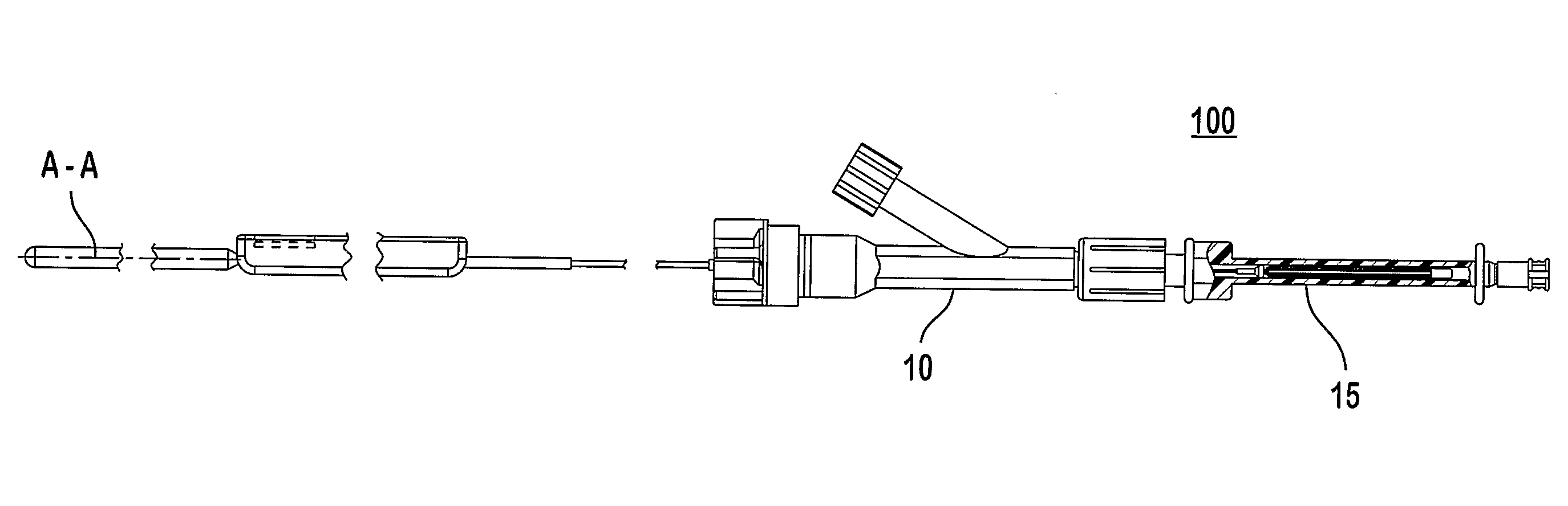
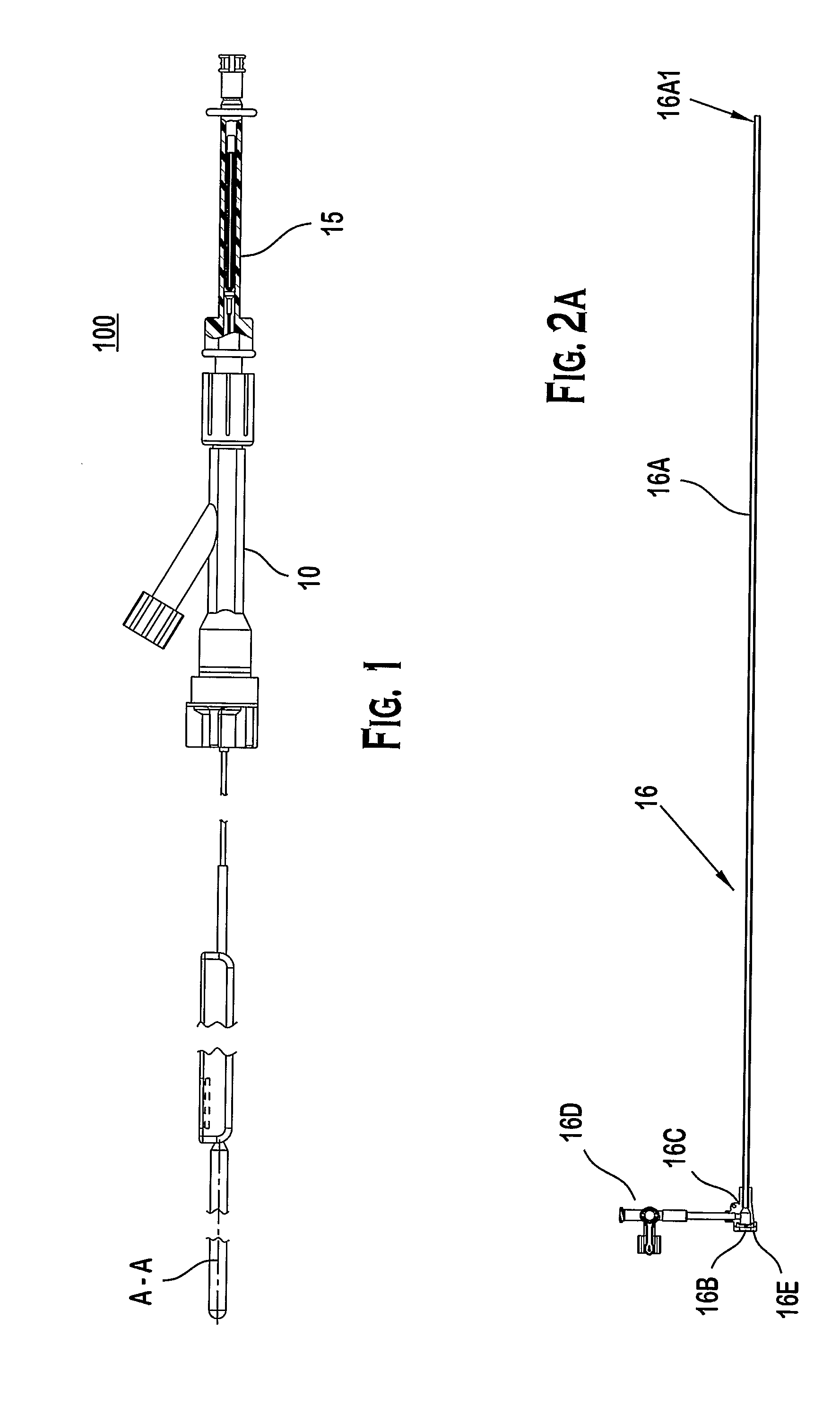
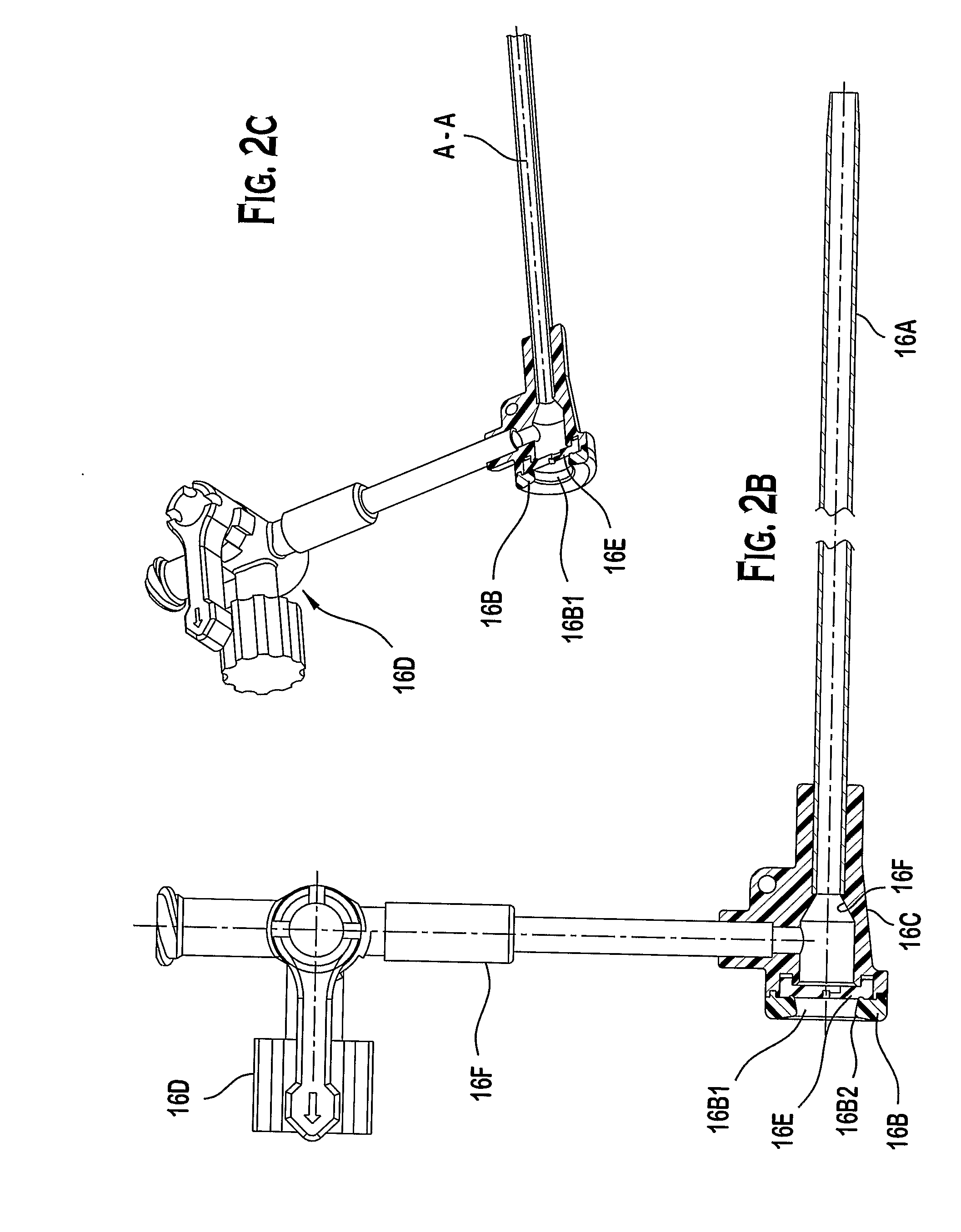
[0027]The blood filter delivery system in the various embodiments mechanically integrates components to safely and reliably deliver and emplace a blood filter, like that illustrated in FIG. 9A, within a patient's blood vessel, such as the inferior vena cava. The system ...


PUM


Abstract

A blood filter delivery system for delivering a filter into a vein includes an introducer (16) and a push rod (12C) with a spline (12E) member disposed along the push rod (12C). The spline member (12E) has a main body, first (12D) and second (12A) boss portions spaced apart along the longitudinal axis to provide a gap for retaining anchor member (14A1) of the filter (14) during delivery via the introducer (16).

Description

PRIORITY DATA AND INCORPORATION BY REFERENCE[0001]This application claims priority to U.S. Provisional Patent Application Ser. No. 60 / 706,596 filed Aug. 9, 2005, entitled “Embolus Blood Clot Filter and Delivery System”, which is incorporated herein by reference in its entirety.FIELD OF THE INVENTION[0002]This invention relates to a filter device that can be placed via a catheter delivery system in a vessel of a mammalian body to reduce the risk of embolisms. If needed, such filter can be removed from the vessel of a mammalian body without causing traumatic damage to the vessel of a mammalian body.BACKGROUND OF THE INVENTION[0003]In recent years, a number of medical devices have been designed which are adapted for compression into a small size to facilitate introduction into a vascular passageway and which are subsequently expandable into contact with the walls of the passageway. These devices, among others, include blood clot filters which expand and are held in position by engageme...

Claims


Application Information

Patent Timeline
Patent Type & Authority Applications(United States)
IPC IPC(8): A61M29/00
CPCA61F2/01A61F2002/011A61M25/0068A61F2230/0093A61F2230/005A61F2230/0067A61F2230/008A61F2002/016A61F2/011A61F2/0105A61F2/0103A61F2220/0008
Inventor CHANDUSZKO, ANDRZEJ J.GRAVES, DAVID M.
Owner CR BARD INC
Why Eureka
Try Eureka