Tendon Cap and method for tendon repair

a tendon cap and tendon technology, applied in the field of tendon cap and method for tendon repair, can solve the problems of increased tendon adhesion formation, traumatic injury to the tendon epitenon, tendon end fraying and traumatic injury, etc., to achieve successful tendon repair surgery, increase the amount of time necessary, and the effect of increasing the time required

Inactive Publication Date: 2009-05-21
WIESMAN IRVIN M +1
View PDF18 Cites 11 Cited by
  • Summary
  • Abstract
  • Description
  • Claims
  • Application Information

AI Technical Summary

Benefits of technology

[0004]A major problem found in this procedure is that the ends of the tendons can fray as they are being pulled back through the pulleys. Prior passing techniques normally utilize sutures or a grasper that manage to pull the tendon through the pulleys along the bone but cause tearing or fraying of the tendon in the process. The fraying can cause damage to the tendon and increase the amount of time necessary to allow the tendons to heal once they have been re-connected. In order to achieve a more successful tendon repair surgery, both ends of the tendons should be free from frayed ends. The surgical procedure also takes more time to complete if there are frayed ends on the tendon, which makes the reattachment more difficult. This can increase the risk of complications.

Problems solved by technology

Passing lacerated or divided tendons underneath pulley systems and through fibro osseous and osseous tunnels can often result in tendon injury, tendon end fraying and traumatic injury to the tendon epitenon.
This has been related to increased tendon adhesion formation, increased bulk at repair sites, decreased repair strength, and increased risk of tendon rupture and loss of tendon excursion upon final healing.
A major problem found in this procedure is that the ends of the tendons can fray as they are being pulled back through the pulleys.
Prior passing techniques normally utilize sutures or a grasper that manage to pull the tendon through the pulleys along the bone but cause tearing or fraying of the tendon in the process.
The fraying can cause damage to the tendon and increase the amount of time necessary to allow the tendons to heal once they have been re-connected.
The surgical procedure also takes more time to complete if there are frayed ends on the tendon, which makes the reattachment more difficult.
This can increase the risk of complications.

Method used


Image

  • Tendon Cap and method for tendon repair
  • Tendon Cap and method for tendon repair

Examples


Embodiment Construction

[0006]The present invention proposes a solution to these problems by providing a tendon cap which is simple for a surgeon to use. The present invention greatly reduces fraying by encompassing the entire end of the tendon in elastic material. The tendon cap can be made of a solid or elastic synthetic or non-synthetic material that encompasses the end of the tendon as described herein.

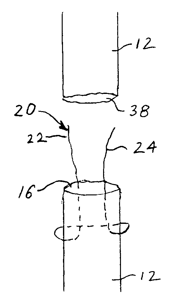
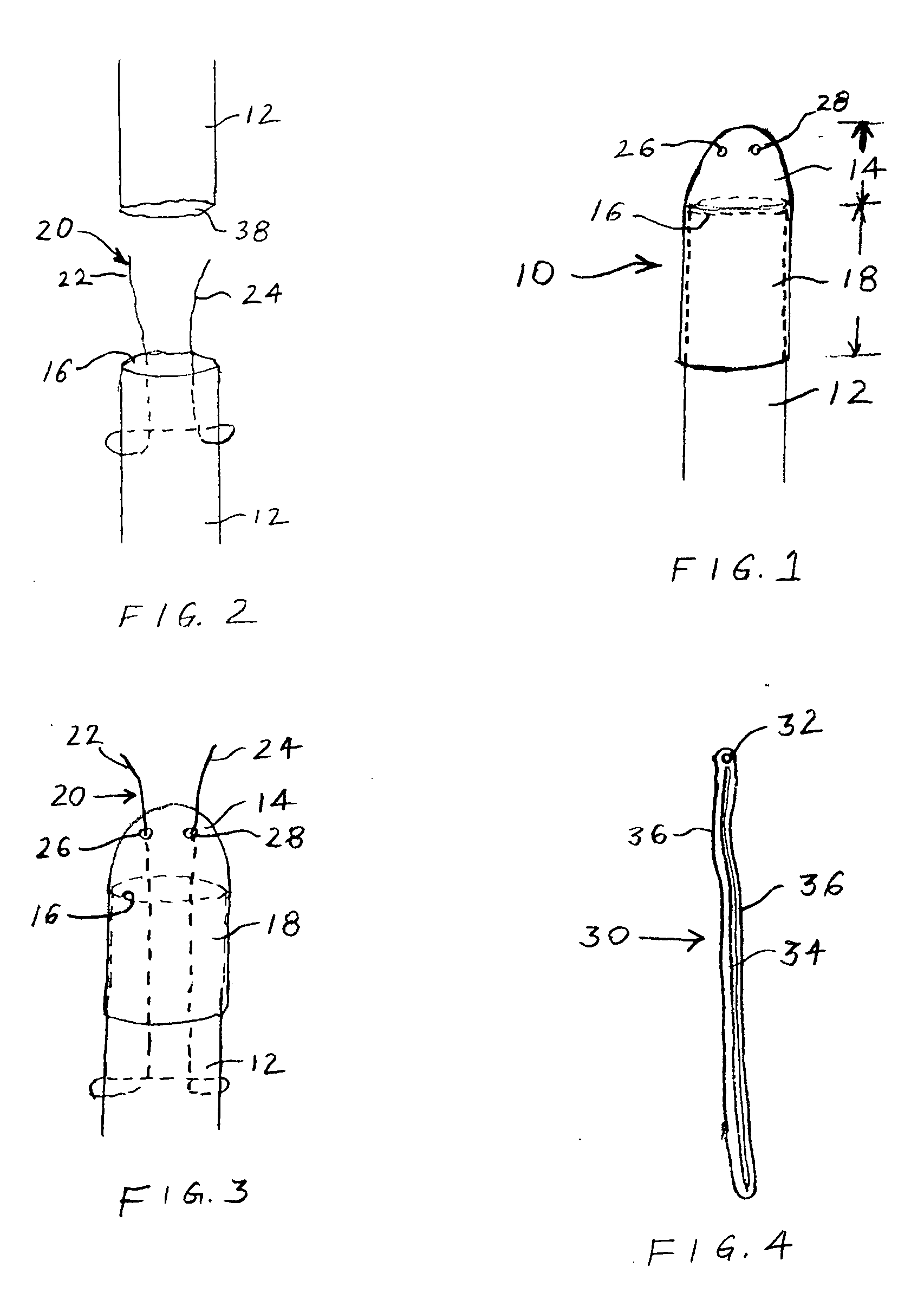
[0007]As seen in FIGS. 1 and 2, a tendon cap 10 is formed from a thin membrane tube with a flexible membrane cap that is placed over an end 16 of a lacerated or divided tendon 12. The lacerated tendon 12 has an opposite end 38 to which end 16 is to be re-attached. There are two zones to the tendon cap 10. There is a head 14 that fits directly over the end 16 of the tendon 12 and a body 18 which shrouds the tendon 12 for some length from the end 16. This protective tendon cap 10 is designed for minimizing friction and injury when passing the tendon 12 under pulley systems or through a fibro osseous / osseou...


PUM


Abstract

A method and apparatus for joining opposite ends of a severed tendon or ligament. A core suture is attached to one of the severed ends. A cap is attached to the severed end by the core suture. The cap protects the severed end from trauma and fraying as it is pulled back toward the opposite severed end of the tendon. The cap is removed prior to reattachment of the severed ends. The cap may have a coating applied to it to reduce friction and add other properties such as improved healing to the tendon after it is reattached.

Description

RELATED APPLICATION[0001]This application claims the priority of U.S. Provisional Application No. 60 / 989,156 filed Nov. 20, 2007.BACKGROUND AND SUMMARY OF THE INVENTION[0002]When a tendon is severed, the proximal tendon end retracts similar to a cut rubber band. A surgeon must reconnect the tendon by guiding at least one severed end through the fibrous / osseous tunnels comprising the pulley system along the bones in the hand and fingers to re-attach the severed proximal and distal ends. The tendon must be safely pulled through the passageways so that minimal tearing or fraying of the ends occurs. Passing lacerated or divided tendons underneath pulley systems and through fibro osseous and osseous tunnels can often result in tendon injury, tendon end fraying and traumatic injury to the tendon epitenon. This has been related to increased tendon adhesion formation, increased bulk at repair sites, decreased repair strength, and increased risk of tendon rupture and loss of tendon excursion...

Claims


Application Information

Patent Timeline
Patent Type & Authority Applications(United States)
IPC IPC(8): A61B17/04A61B19/00
CPCA61B17/1146A61B17/04
Inventor WIESMAN, IRVIN M.BEAR, BRIAN J.
Owner WIESMAN IRVIN M
Why Eureka
Try Eureka