[0009]The blocking end of the blocker may be arcuate in shape such that it generally follows the
arcuate shape of the bone screw hole. The
arcuate shape of the blocking end may correspond to the
arcuate shape of the bone screw hole, or may differ somewhat from the arcuate shape of the bone screw hole. In one aspect of the present invention, the blocker may extend over the periphery of bone screw hole by about 25% of the perimeter. In another aspect, it is about ⅓ of the periphery. Of course, as long as the blocker can be moved upon the
insertion of the bone screw, the coverage on the perimeter of the bone screw hole may be larger.
[0011]In connection with another aspect of the present invention, a method may be employed practicing the steps of providing a plate having a blocker which extends over a portion of a bone screw receiving hole in a bone plate, inserting a bone screw through the bone screw receiving hole, and simultaneously moving the blocker away from the screw hole to allow
insertion of the bone screw, continuing insertion until the bone screw passes the blocker to allow the blocker to move back into the blocking position, and manipulating the
cam from an open orientation to a closed orientation at which movement of the blocker from the blocking position is substantially prevented.
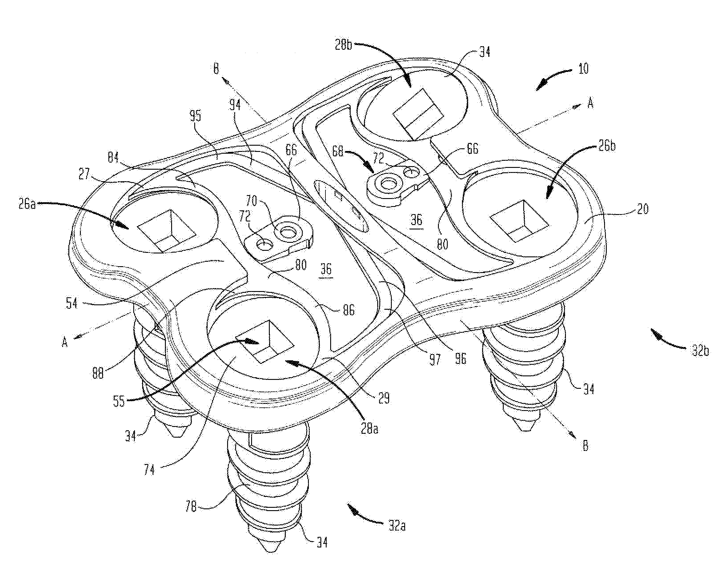
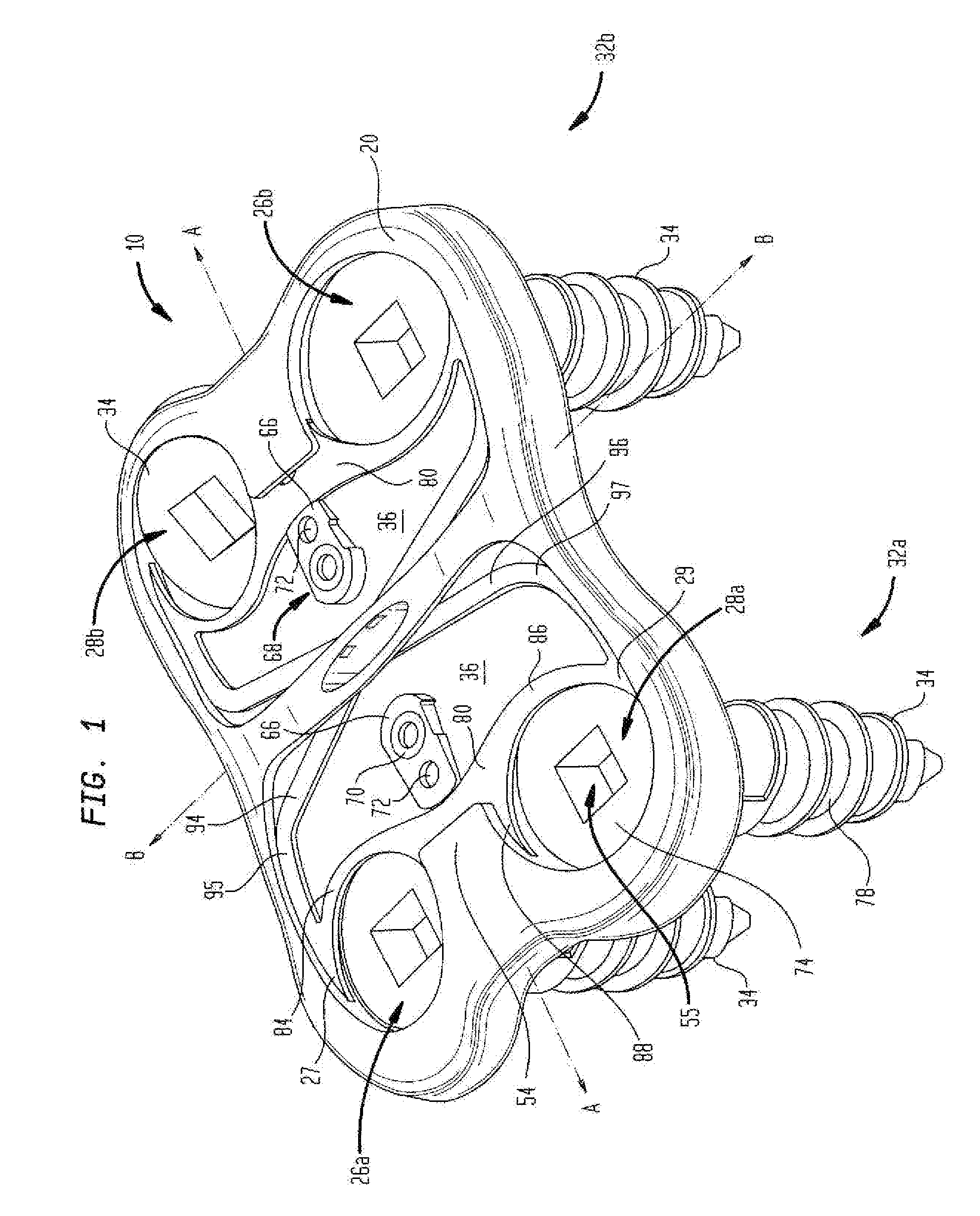
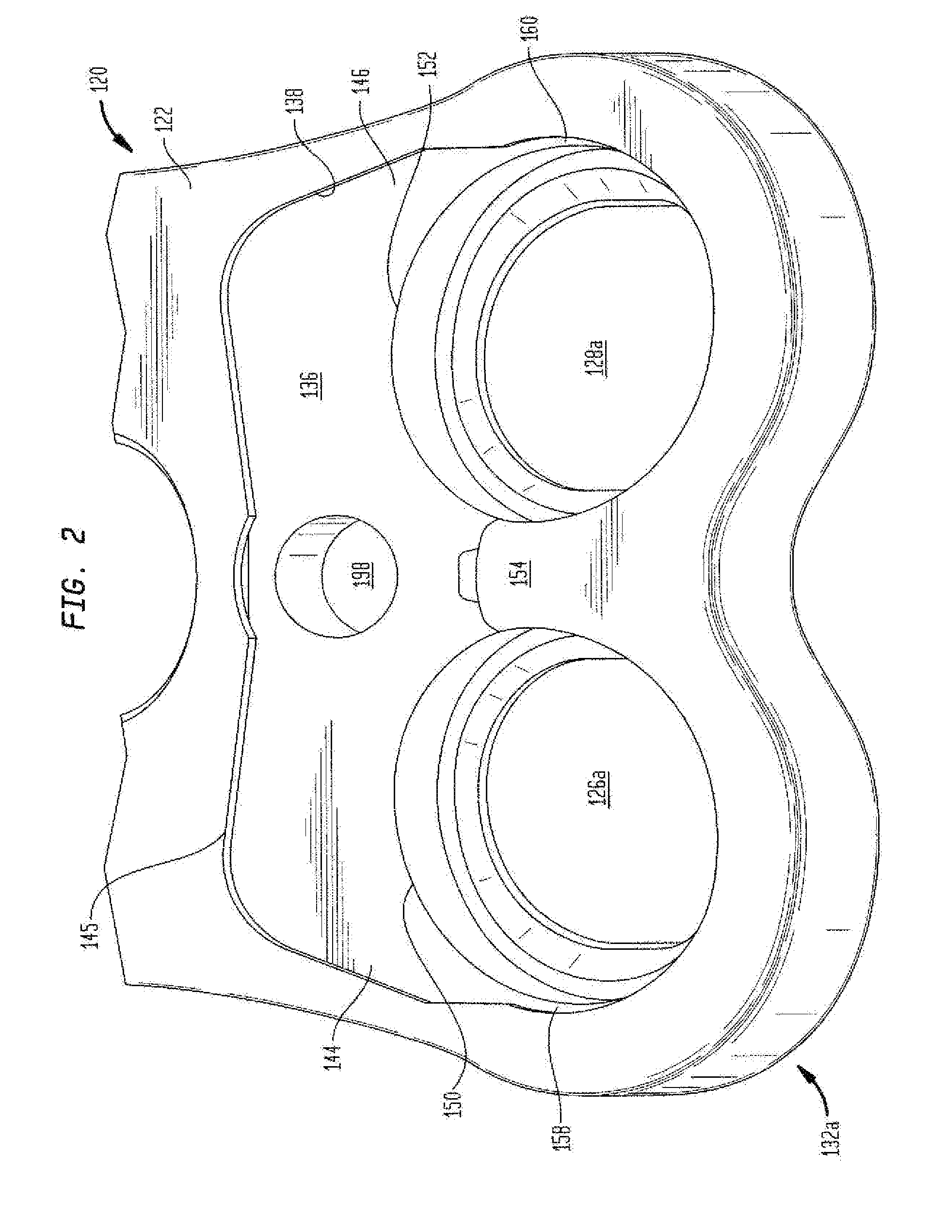
[0012]Yet a further aspect of the present invention may be practiced by a bone plate having a top surface and a lower surface and at least two bone screw receiving holes therethrough, undercuts in the periphery of at least a portion of the bone screw receiving holes, a blocker housed within the recess, the blocker having blocking ends which extend over portions of the respective bone screw receiving holes such that the blockers in a blocking position at which it is above a bone screw seated in the plate and in a bone during implantation and can block the bone screw from backing out of the bone plate should the bone screw loosen, the blocker being movable from the blocking position upon insertion of the respective bone screw, whereby the bone screw causes the blocker to move away from the bone screw receiving hole to allow insertion until the bone screw passes the blocker and the blockers thereby permitted to return to the blocking position. In connection with this aspect of the present invention, the blocker may be seated in a recess which is coextensive with the grooves around the least portion of the periphery of the bone screw receiving holes, and the recess in the plate may include a further groove opposition the bone screw receiving holes. The aspect of the present invention may also include a blocker fixing device which, after insertion of the bone screws in the bone plate and into bone, can be actuated by a surgeon to prevent the blocker from moving from the blocking position.
[0016]In connection with this aspect of the present invention, the hinged member may include a flexible portion which facilitates locking of the hinged member in the blocking position following movement from the open position and after a bone screw is inserted into the bone screw hole.
[0019]The present invention provides a plate
system wherein the bone screw, if loosened after implantation, is blocked from loosening beyond the blocker (alternatively, called the spring bar). The present invention also provides a blocking
system wherein the blocker operates without requiring further actuation beyond implanting the screw past the blocker. A secondary action of a
cam is provided to ensure that the movement of the bone screw does not displace the blocker upon potential backout of the bone screw. The present invention further provides the surgeon with a tactile and
visual feedback as to the position of the bone screw. The feedback may result from the loss of the force exerted by the blocker on the head of the screw when the screw is tightened past the blocker. The feedback may include an audible click when the screw moves past the blocker. The feedback may also result from
visual observation of the position of the blocker. The blocker may be
colored to enhance such
visual feedback. The feedback also comes from the secondary action of manipulating a feedback device, i.e., the
cam. The simple secondary action of manipulating the cam being, in and of itself, a feedback to the surgeon, even beyond any tactile feedback from the cam.

