
Vehicle Display Apparatus

a technology for display devices and vehicles, applied in the direction of process and machine control, navigation instruments, instruments, etc., can solve the problems of degrading the manipulability/operation of the region between the image display device and the transparent display input device may not be used as an available space, etc., to achieve good visibility

Active Publication Date: 2009-05-21
TOYOTA JIDOSHA KK
View PDF3 Cites 49 Cited by
  • Summary
  • Abstract
  • Description
  • Claims
  • Application Information

AI Technical Summary

Benefits of technology

[0008]The present invention provides a vehicle display apparatus that allows the operator to operate the image display device installed around an instrument panel with good visibility, from a remote position where the operator cannot operate the image display device, by manipulating a transparent display input device installed nearer to the operator than to the instrument panel. The vehicle display apparatus can also provide an available space at the rear side of the transparent display input device.
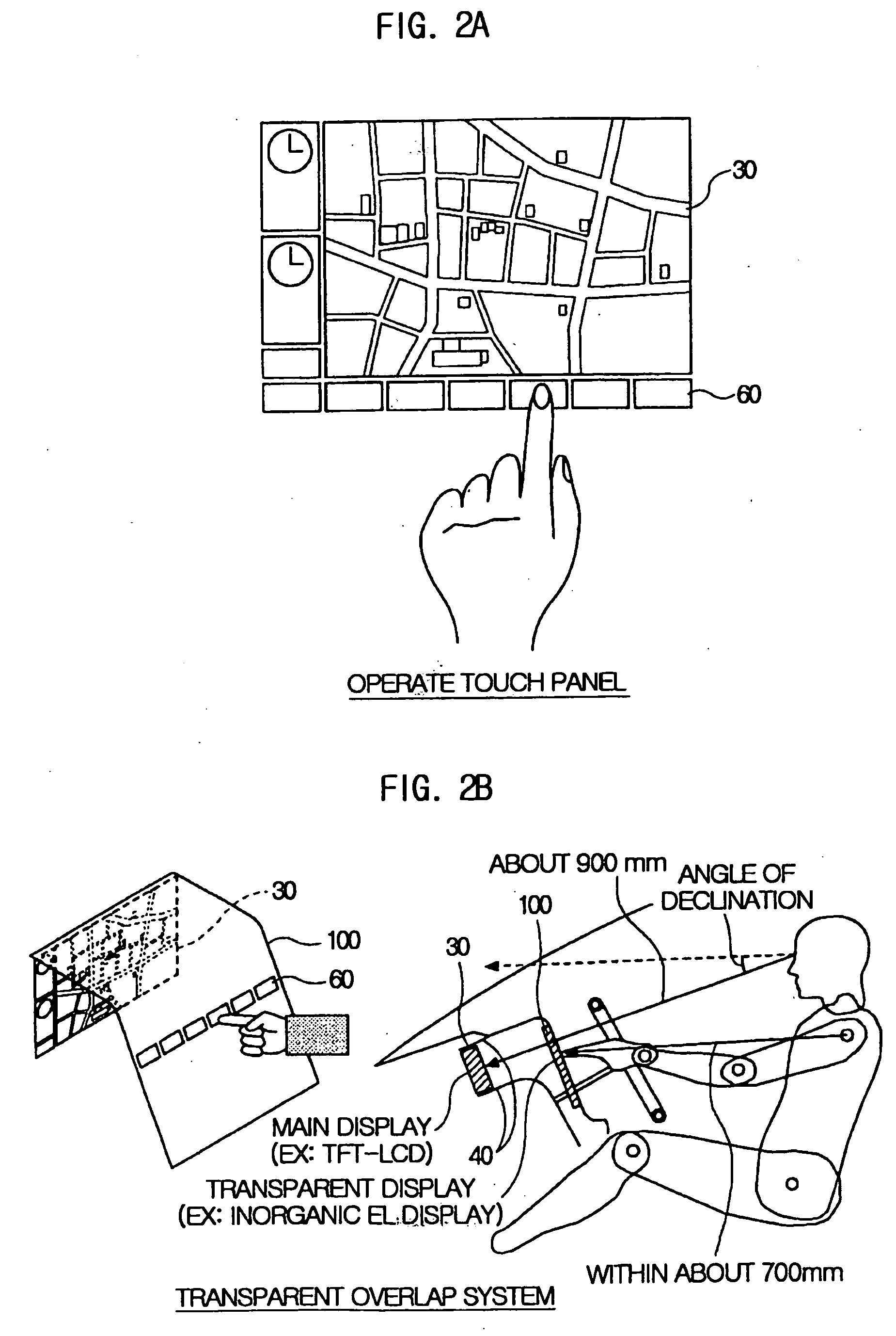
[0009]A vehicle display apparatus in accordance with a first aspect of the invention includes: a display device disposed in an instrument panel; and a transparent display input device for the display device, the transparent display input device extending substantially from a surface portion of the instrument panel to an upper portion of a center console. Hence, manipulability and operability of the display apparatus is improved as an operator is allowed to manipulate the transparent display input device disposed closer to the operator than to the display device.

Problems solved by technology

As a result, the driver often feels inconvenient to see the display screen.
As a result, manipulability / operability of the transparent display input device may be also degraded.
Furthermore, due to the integral structure attached to the instrument panel, a region between the image display device and the transparent display input device may not be used as an available space.

Method used


Image

  • Vehicle Display Apparatus
  • Vehicle Display Apparatus
  • Vehicle Display Apparatus

Examples


Embodiment Construction

[0036]Various embodiments of the present invention will now be described in detail with reference to the accompanying drawings.

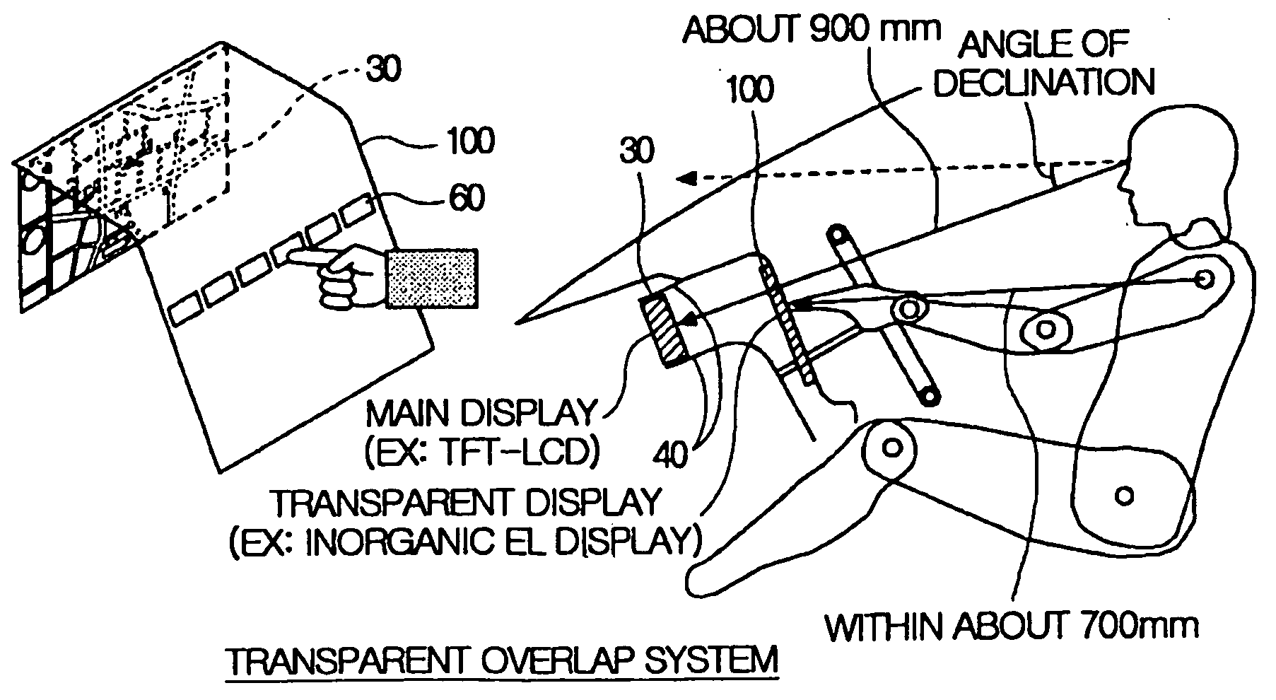
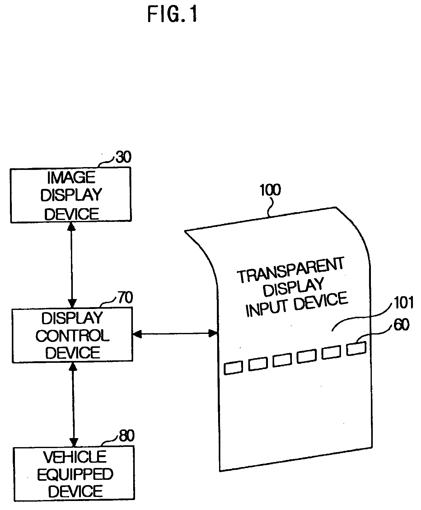
[0037]FIG. 1 illustrates a functional block diagram of one example of main configuration of a vehicle display apparatus and related devices in accordance with a first embodiment of the present invention. As shown in FIG. 1, the vehicle display apparatus includes a transparent display input device 100, a display control device 70, and an image display device 30 displaying information images, such as maps. The vehicle display apparatus also includes a vehicle-equipped device 80 as a related device, performing predetermined functions, such as an air-conditioning function, an audio function, and a navigation function. The transparent display input device 100 may display input switches 60 on a display panel 101.

[0038]The display control device 70 is configured with a micro computer as a key element. That is, the display control device 70 includes: a central proce...


PUM


Abstract

A vehicle display apparatus includes an image display device (30) disposed in a region where an operator is unable to operate the display apparatus (30), and a transparent display input device (100) installed in a region from a surface portion of the instrument panel (40) to an upper portion of a center console (50). The vehicle display apparatus is designed to allow the operator to operate the image display device (30) from a remote position by manipulating the transparent display apparatus (100) disposed near the operator.

Description

BACKGROUND OF THE INVENTION[0001]1. Field of the Invention[0002]The present invention relates to a vehicle display apparatus that allows remote operation of an image display device by operating a transparent display input device near the operator, wherein the image display device is mounted at a distance from an operator of a vehicle, such that the operator cannot manipulate the image display device.[0003]2. Description of the Related Art[0004]In many occasions, vehicles are equipped with a vehicle display apparatus with an image display device provided with functions of displaying maps of geographical regions and navigating a target geographical region. Operational switches of a touch panel are displayed on a display screen of the image display device, and an operator usually manipulates the image display device by touching the operational switches.[0005]However, if the operational switches are displayed on the same display portion of the image display device that represents geogra...

Claims


Application Information

Patent Timeline
Patent Type & Authority Applications(United States)
IPC IPC(8): G06F19/00B60K35/10B60R11/02H01H15/02H01H19/02
CPCB60K35/00B60K2350/1024B60K2350/2034G01C21/365B60K2350/901B60K2350/903B60K2350/925B60K2350/355B60K35/10B60K2360/117B60K2360/113B60K2360/143B60K2360/331B60K35/80B60K2360/55B60K35/656B60K35/60B60K2360/774B60K35/654G06F3/041
Inventor KUMON, HITOSHIISHIZAKI, SATORU
Owner TOYOTA JIDOSHA KK
Learn More