Electronic Pneumatic Spring Controller for Reducing Air Consumption and Rapidly Adjusting the Setpoint Level

a pneumatic spring controller and electronic technology, applied in the field of rail vehicles, can solve the problems of corresponding air consumption and configuration conflict, and achieve the effect of preventing leakage currents and not compromising the operation reliability or safety of the rail vehicl

Inactive Publication Date: 2009-05-28
SIEMENS AG OESTERR
View PDF17 Cites 1 Cited by
  • Summary
  • Abstract
  • Description
  • Claims
  • Application Information

AI Technical Summary

Benefits of technology

[0014]The at least one switching means can be brought into an open switching position at defined time intervals so that for a certain length of time the system behaves like a conventional system. Leakage currents can be very efficiently prevented in this way. The at least one switching means can also be controlled taking into account a measured vertical and / or lateral acceleration of the rail vehicle, the switching means being opened only when the rail vehicle is located on a straight section of track so as not to compromise the operating reliability or safety of the rail vehicle. The vertical and / or lateral acceleration of the rail vehicle can be measured by means of corresponding acceleration sensors.

Problems solved by technology

These requirements result in a configuration conflict, for the resolution of which valves having special valve characteristic curves are used according to the prior art.
One of the disadvantages of the solution according to the prior art is that when the vehicle is traveling along the track the mechanical valve may sometimes be fully open, e.g. in curves, which results in a corresponding consumption of air.

Method used


Image

  • Electronic Pneumatic Spring Controller for Reducing Air Consumption and Rapidly Adjusting the Setpoint Level
  • Electronic Pneumatic Spring Controller for Reducing Air Consumption and Rapidly Adjusting the Setpoint Level

Examples


Embodiment Construction

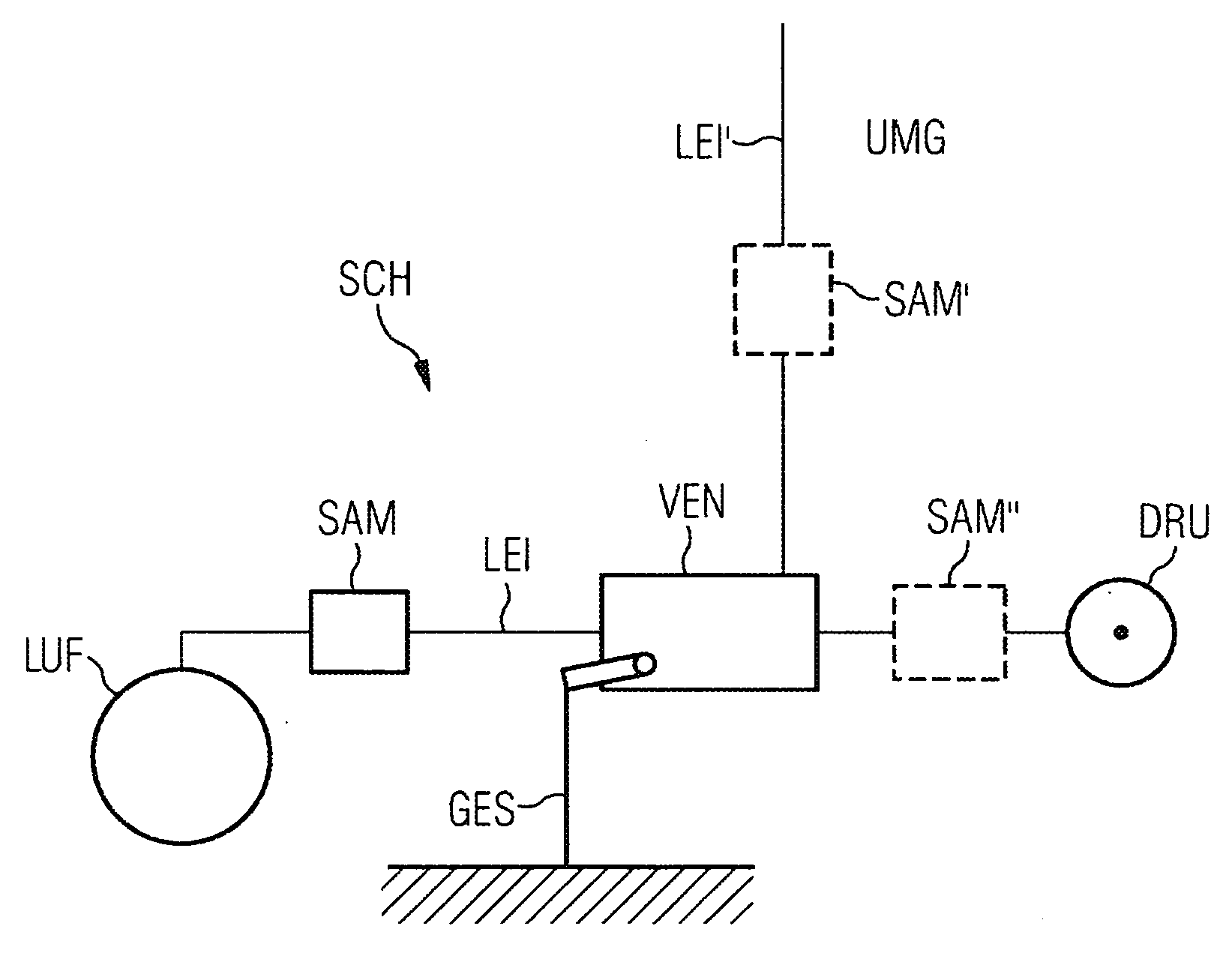
[0024]As shown in the FIGURE, a rail vehicle according to the invention has at least one pneumatic spring LUF which forms a secondary spring for supporting a railcar body. At least one mechanically actuatable valve VEN is disposed in at least one air supply / discharge line LEI between a pressure source DRU and the pneumatic spring LUF or the pneumatic spring LUF and an environment UMG for the purpose of controlling the air exchange. The mechanical valve VEN can be actuated by way of an arrangement of levers GES disposed on an undercarriage of the rail vehicle SCH. If the rail vehicle subsides due to being loaded, the valve VEN is opened by means of the lever arrangement GES toward the pressure source DRU, resulting in an inflow of air from the pressure source DRU into the pneumatic spring LUF. If the pneumatic spring LUF rebounds beyond a setpoint position, it is vented to the environment UMG by way of the valve VEN.

[0025]According to a first variant of the invention, at least one sw...


PUM


Abstract

Disclosed is a railway vehicle comprising at least one pneumatic spring for supporting a body. At least one mechanically actuated valve is disposed in at least one air supply/discharge tube of the at least one pneumatic spring in order to control air exchange of the at least one pneumatic spring. At least one switching means is provided between the at least one mechanical valve and the at least one pneumatic spring in the at least one air supply/discharge tube in order to control air exchange. Alternatively, at least one switching means is arranged between the at least one mechanical valve and at least one pressure source while at least one additional switching means is placed in a tube that connects the at least one mechanical valve to an environment in order to control air exchange.

Description

CROSS REFERENCE TO RELATED APPLICATIONS[0001]This application is the US National Stage of International Application No. PCT / EP2006 / 069382, filed Dec. 6, 2006 and claims the benefit thereof. The International Application claims the benefits of Austrian application No. A 407 / 2006 filed Mar. 13, 2006, both of the applications are incorporated by reference herein in their entirety.FIELD OF INVENTION[0002]The invention relates to a rail vehicle having at least one pneumatic spring for supporting a railcar body, wherein at least one mechanically actuatable valve is disposed in at least one air supply / discharge line of the at least one pneumatic spring for the purpose of controlling the air exchange of the at least one pneumatic spring.[0003]The invention also relates to a method for operating at least one pneumatic spring for supporting a railcar body of a rail vehicle, wherein at least one mechanically actuatable valve is disposed in at least one air supply / discharge line of the at least...

Claims


Application Information

Patent Timeline
Patent Type & Authority Applications(United States)
IPC IPC(8): B61F5/10B60G17/052
CPCB60G17/0525B60G2400/104B61F5/144B60G2400/204B60G2400/252B60G2400/106
Inventor KITZMULLER, CHRISTIANSIX, KLAUSTEICHMANN, MARTINWALTENSDORFER, HERWIGWEILGUNI, GERHARD
Owner SIEMENS AG OESTERR
Why Eureka
Try Eureka