Driving support device, wearable device, driving support system, driving support method, and computer-readable recording medium
a technology of driving support and wearable devices, which is applied in the direction of driver input parameters, instruments, transportation and packaging, etc., can solve the problems and achieve the effect of compromising safety during driving
- Summary
- Abstract
- Description
- Claims
- Application Information
AI Technical Summary
Benefits of technology
Problems solved by technology
Method used
Image
Examples
first embodiment
[0034]Configuration of Driving Support Device
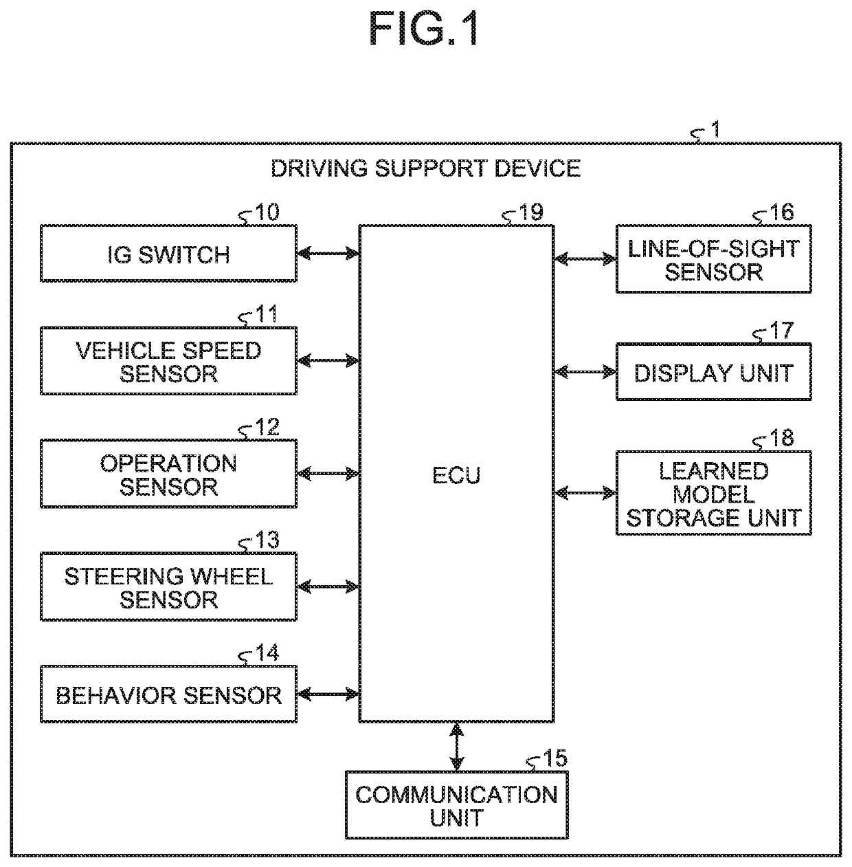
[0035]FIG. 1 is a block diagram illustrating a functional configuration of a driving support device installed in a vehicle according to a first embodiment. A driving support device 1 illustrated in FIG. 1 is installed in a vehicle, and cooperates with other Electronic Control Units (ECUs) installed in the vehicle to support driving of a driver in the vehicle. The driving support device 1 illustrated in FIG. 1 includes an ignition switch 10 (hereinafter referred to as an “IG switch 10”), a vehicle speed sensor 11, an operation sensor 12, a steering wheel sensor 13, a behavior sensor 14, a communication unit 15, a line-of-sight sensor 16, a display unit 17, a learned model storage unit 18, and an ECU 19.
[0036]The IG switch 10 receives instructions of start and stop of an electric system such as an engine or a motor. The IG switch 10 starts an IG power supply upon being turned ON, and stops the IG power supply upon being turned OFF.
[0037]The...
second embodiment
[0080]Next, a second embodiment will be described. In the first embodiment described above, the driving support information is displayed and projected in the vehicle by the display unit 17. In the second embodiment, the driving support information is displayed using a wearable device. In the following, components that are the same as those in the driving support device 1 according to the first embodiment described above are denoted by the same reference numerals, and detailed descriptions thereof will be omitted.
[0081]Configuration of Driving Support System
[0082]FIG. 7 is a diagram illustrating a schematic configuration of a driving support system according to the second embodiment. FIG. 8 is a block diagram illustrating a functional configuration of the driving support system according to the second embodiment. FIG. 9 is a diagram illustrating a schematic configuration of a wearable device according to the second embodiment.
[0083]A driving support system 1000 illustrated in FIGS. 7...
first modification
of Second Embodiment
[0127]Next, a first modification of the second embodiment will be described. In the first modification of the second embodiment, an example of application to a grip handle will be described.
[0128]FIG. 13 is a diagram schematically illustrating a display position of the driving support information output by the ECU 19 to be displayed by the wearable device 2, according to the first modification of the second embodiment.
[0129]As illustrated in FIG. 13, the ECU 19 outputs driving support information M60 to the wearable device 2 so that the driving support information M60 is projected and displayed on a region right above a grip handle 103A, in the visual field of the driver. The driving support information M60 includes a recommended steering amount T60 for the grip handle 103A from a reference position (horizontal position), and angle information T61, T62, and T63 indicating an angle from the reference position.
[0130]According to the first modification of the second...
PUM
 Abstract
Description
Claims
Application Information
 - R&D
- Intellectual Property
- Life Sciences
- Materials
- Tech Scout
- Unparalleled Data Quality
- Higher Quality Content
- 60% Fewer Hallucinations
Browse by: Latest US Patents, China's latest patents, Technical Efficacy Thesaurus, Application Domain, Technology Topic, Popular Technical Reports.
© 2025 PatSnap. All rights reserved.Legal|Privacy policy|Modern Slavery Act Transparency Statement|Sitemap|About US| Contact US: help@patsnap.com


