Latent heat recovery-type water heater

Inactive Publication Date: 2009-05-28
NORITZ CORP
View PDF8 Cites 25 Cited by
  • Summary
  • Abstract
  • Description
  • Claims
  • Application Information

AI Technical Summary

Benefits of technology

[0027]The present invention provides the latent heat recovery-type water heater capable of certainly preventing drain generated by heat exchange from being discharged out of the exhaust portion with entrained by a flow of the combustion gas.

Problems solved by technology

Such a kind of water heater uses excellent and expensive anticorrosive materials as materials of members such as a heat exchanger due to a strong acidity resulting from drain, which is generated by recovering latent heat and exposed to combustion gas.

Method used


Image

  • Latent heat recovery-type water heater
  • Latent heat recovery-type water heater
  • Latent heat recovery-type water heater

Examples


Embodiment Construction

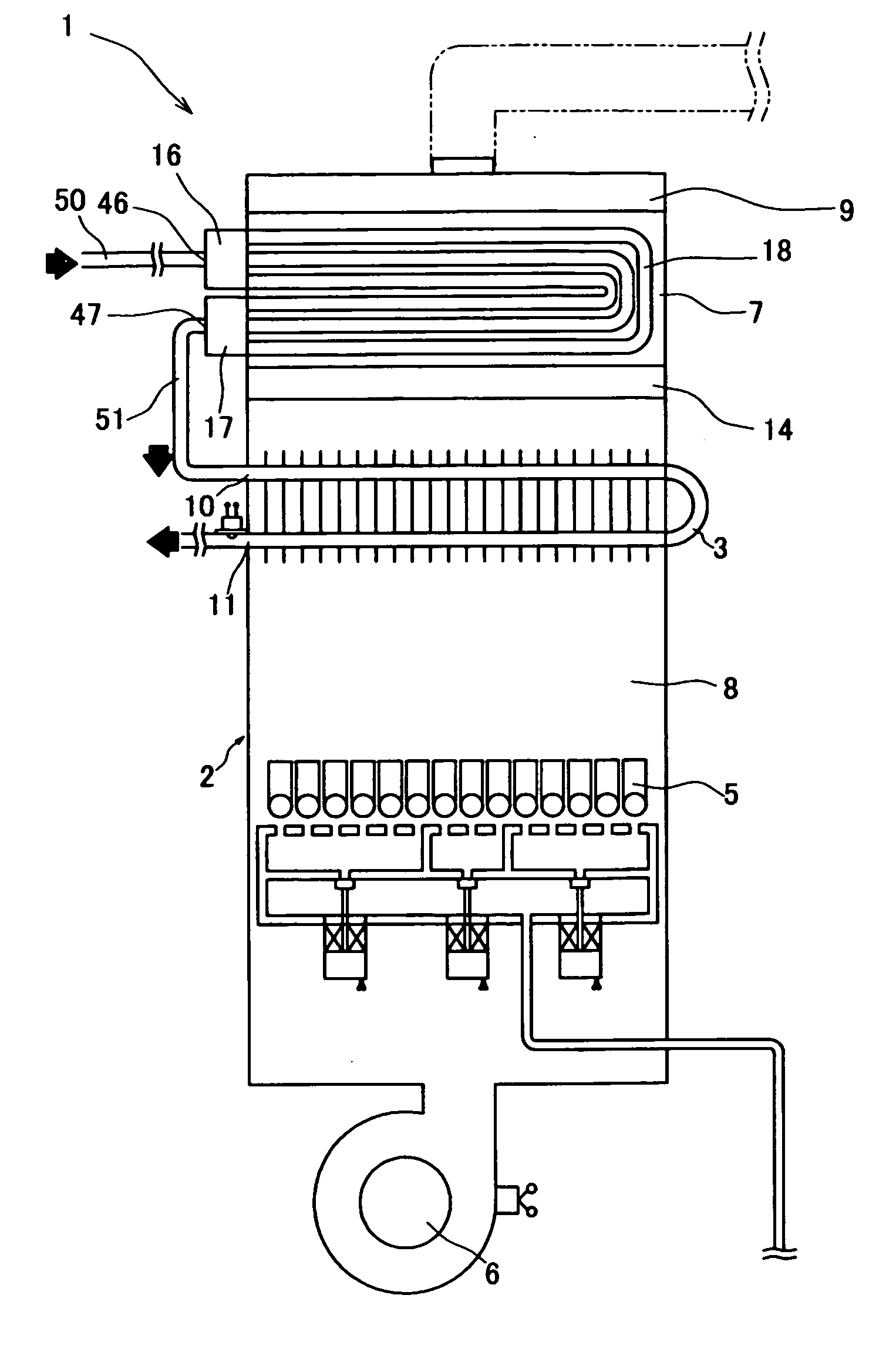
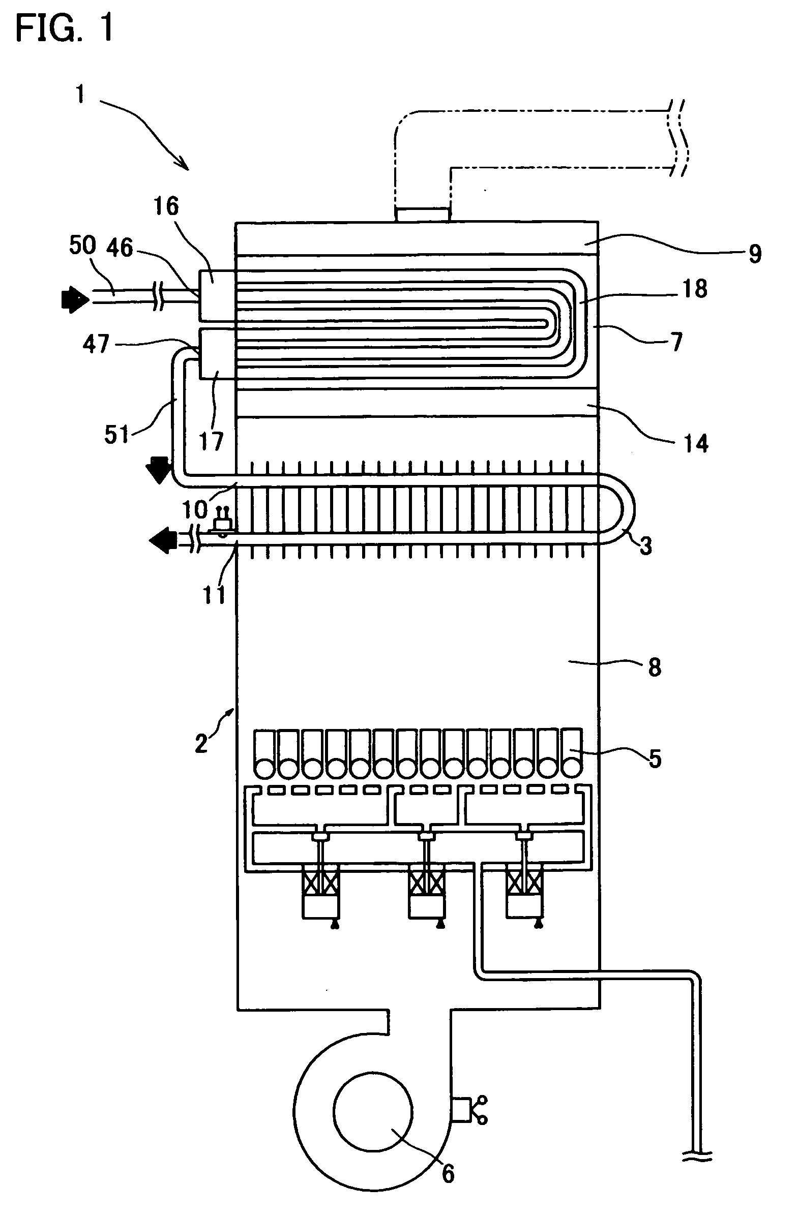
[0034]Now, a latent heat recovery-type water heater 1 (hereinafter referred to as a water heater 1) of an embodiment of the present invention will be described below in detail, making reference to the accompanying drawings. As shown in FIG. 1, the water heater 1 mainly consists of a shell 2 provided with a primary heat exchanger (first heat exchanger) 3 for mainly recovering sensible heat contained in combustion gas, a secondary heat exchanger (second heat exchanger) 7 for mainly recovering latent heat contained in combustion gas, a burner (combustion means) 5, a fan 6, and an exhaust portion 9. The secondary heat exchanger 7 is located downstream of the primary heat exchanger 3, that is, at an upper part in FIG. 1. The exhaust portion 9 is located downstream in a flow direction of the combustion gas, that is, above the secondary heat exchanger 7.

[0035]The primary heat exchanger 3 is designed to carry out heat exchange with the combustion gas flowing in a combustion gas passage 8 in...


PUM


Abstract

So as to provide a latent heat recovery-type water heater capable of certainly preventing drain generated by heat exchange from being discharged out of an exhaust portion through an outlet with entrained by a flow of combustion gas, an exhaust portion 9 is formed by an exhaust portion constituting-body 25 attached above a secondary heat exchanger 7. The exhaust portion 9 includes therewithin a deflector 26 and a distribution board 27 opposed to the deflector 26. The deflector 26 has a deflection board 30 extending substantially vertically downward from a top face 9a of the exhaust portion 9, so as to form a gap 35 between a lower end of the board 30 and a bottom face 9b of the exhaust portion 9. A flowing direction of combustion gas introduced into the exhaust portion 9 through an opening 21 of the bottom face 9b is deflected by passing through the gap 35, and the combustion gas flows toward the distribution board 27. The combustion gas hits on the distribution board 27 to be distributed within the exhaust portion 9, thereafter being discharged through an exhaust opening 23.

Description

BACKGROUND OF THE INVENTION[0001]1. Field of the Invention[0002]The present invention relates to a latent heat recovery-type water heater capable of recovering not only sensible heat but also latent heat contained in combustion gas. Herein, in the present application, the term “water” includes cold water and hot water, if not otherwise specified.[0003]2. Description of Related Art[0004]Conventionally, a latent heat recovery-type water heater as disclosed in the below-identified patent document has been provided. Such a kind of water heater uses excellent and expensive anticorrosive materials as materials of members such as a heat exchanger due to a strong acidity resulting from drain, which is generated by recovering latent heat and exposed to combustion gas.[0005]Patent Document 1: JP 11-148642ASUMMARY OF THE INVENTION[0006]Problems to be Solved by the Invention[0007]Herein, the above-mentioned latent heat recovery-type water heater may be arranged in such a manner that a combustio...

Claims


Application Information

Patent Timeline
Patent Type & Authority Applications(United States)
IPC IPC(8): F22B1/18F24H1/00
CPCF22D1/10Y02B30/102F24H8/00F24H1/40Y02B30/00
Inventor ASAKURA, HIROSHIYAMAMOTO, SHIGEHIROISHIKADO, MASAMITU
Owner NORITZ CORP
Why Eureka
Try Eureka