Painting machine

a painting machine and solvent technology, applied in the field of painting machines, can solve the problems of requiring a large amount of solvent to clean a painting machine of this type, and achieve the effect of greatly reducing the amount of solven

Inactive Publication Date: 2009-05-28
SIEMENS AG
View PDF3 Cites 13 Cited by
  • Summary
  • Abstract
  • Description
  • Claims
  • Application Information

AI Technical Summary

Benefits of technology

[0011]The great advantage is that, by comparison with the prior art, the amount of solvent is greatly reduced, by paint residues as well as the first mixed products of paint and solvent being conveyed out of the painting machine into the disposal container at the beginning of the cleaning phase.
[0012]A further advantage is that, by comparison with the prior art, no compressed air source to drive a separate circulation pump for the solvent is needed.

Problems solved by technology

However a disadvantageously large amount of solvent is required to clean a painting machine of this type.
This is regrettable, given the increasing demands for environmental protection.

Method used


Image

  • Painting machine
  • Painting machine
  • Painting machine

Examples


Embodiment Construction

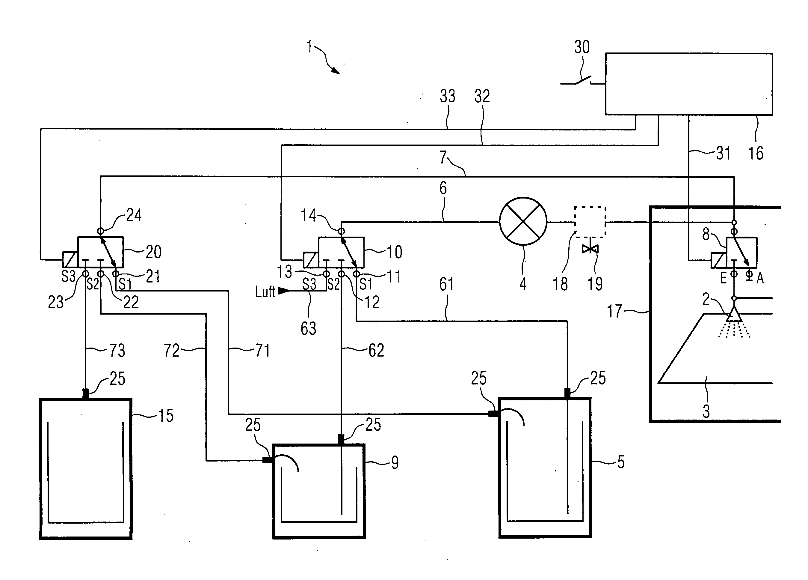
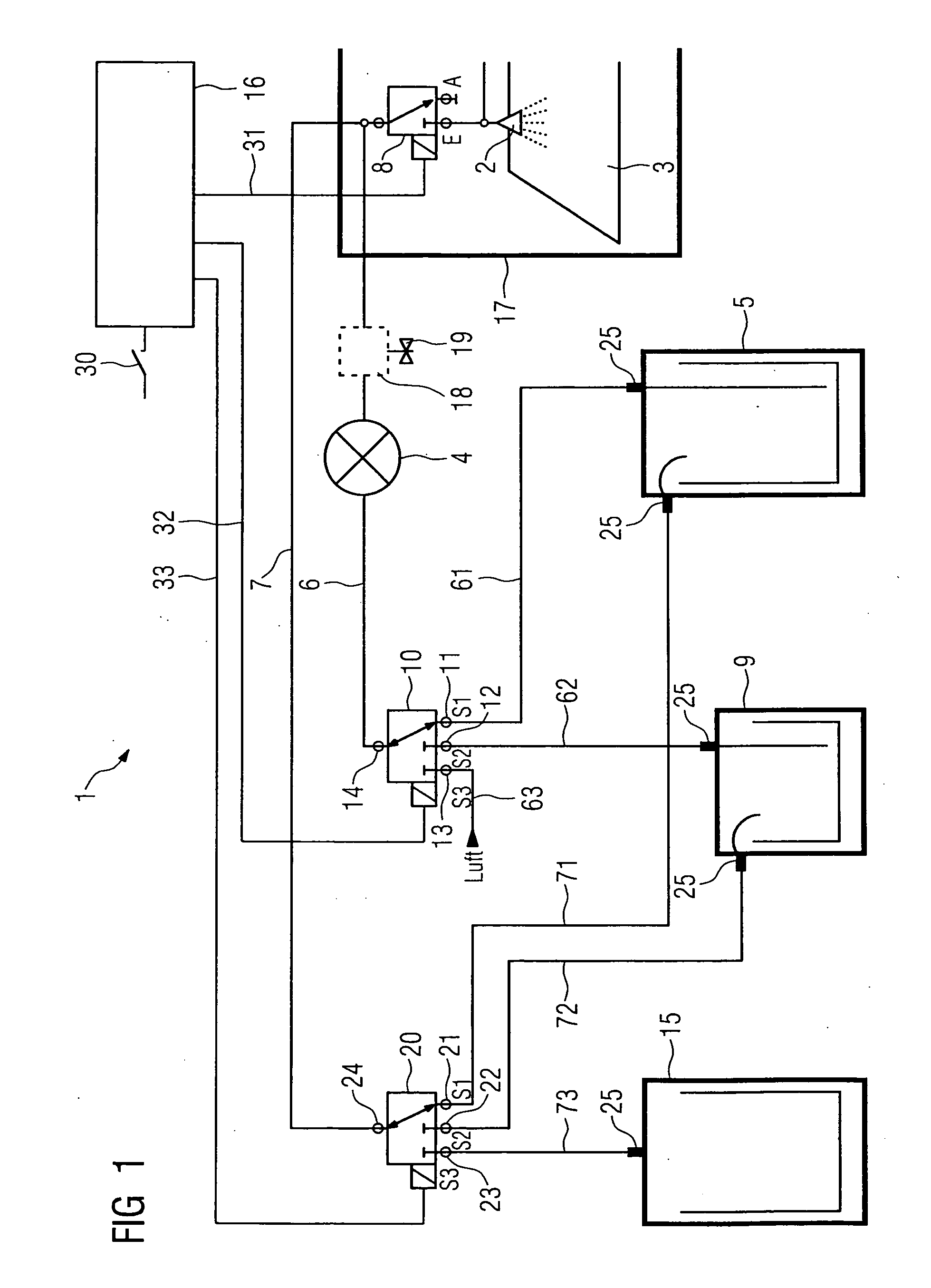
[0024]FIG. 1 shows the typical structure of a painting machine 1. The right hand part of FIG. 1 shows a section of a spray cabin 17. Typically only one spray head 2 for painting an object 3 is arranged in the spray cabin. It can be moved by means of a movement mechanism not shown in further detail for painting the object 3. The object 3 for example can be a printed circuit board which is provided in this way with protective paint. The spray head 2 is connected on its input side to a feed line 6. A pump 5 for conveying at least the paint is provided in the feed line 6. The pump 4 is connected on its input side to a paint container 5 from which the paint is sucked in. On the output side the spray head 2 is connected to a return line 7 for return of the paint not sprayed. Via this line the paint is conveyed back to the paint container 5.

[0025]Shown in the lower part of FIG. 1 is the paint container5, a solvent container 15 as well as a disposal container 15 for disposing of paint and s...


PUM


Abstract

A painting machine having a spray head for painting an object, a pump for conveying paint from a paint container via a feed line to the spray head and back via a return line to the paint container, the feed and return lines connected to a solvent container with a solvent for flush cleaning the painting machine. The feed and return lines are connected to a disposal container for disposing of paint and solvent residues, and at their respective container-side end to a first and second controllable multiway valve for switching the feed and return lines to the paint container, solvent container or disposal container. The painting machine has a control device for controlling the multiway valve such that execution of the consecutive operations of disposal of the paint, filling with solvent, flushing out the painting machine, disposing of the solvent, refilling with paint and also further conveyance of the paint are automated.

Description

CROSS REFERENCE TO RELATED APPLICATIONS[0001]This application claims priority of European Patent Office application No. 07023082.6 EP filed Nov. 28, 2007, which is incorporated by reference herein in its entirety.FIELD OF INVENTION[0002]The invention relates to a painting machine with at least one spray head for painting one or more objects and with a pump for conveying at least paint from a paint container via a feed line to the spray head and back via a return line to the paint container. For cleaning the painting machine, the feed line and the return line can be connected to a solvent container with a solvent.BACKGROUND OF INVENTION[0003]These types of painting machine are used for example for painting components, housing parts, motor vehicles or printed circuit boards.[0004]A method and also a system for cleaning a painting system are known from U.S. Pat. No. 7,156,112 B2. The cleaning system can be connected on the input side to a return line and on the output side to a feed li...

Claims


Application Information

Patent Timeline
Patent Type & Authority Applications(United States)
IPC IPC(8): B05B15/02B05B15/55
CPCB05B9/0403H05K3/0091B05B15/025B05B12/14B05B15/55B05B15/58B05B14/00
Inventor HOFFMANN, ANDREAS
Owner SIEMENS AG
Why Eureka
Try Eureka