System and method of mounting a removable and adjustable photovoltaic ballast frame device

a photovoltaic ballast and adjustable technology, applied in the direction of light support devices, washstands, scaffold accessories, etc., can solve the problems of reducing the effectiveness of expensive roofing surfaces, many parts of prior art pv module ballast frame structures, and multiple penetrations into roofing structures upon which they are installed, so as to achieve the effect of fewer components and convenient assembly

Inactive Publication Date: 2009-05-28
UNIRAC INC
View PDF10 Cites 68 Cited by
  • Summary
  • Abstract
  • Description
  • Claims
  • Application Information

AI Technical Summary

Benefits of technology

[0004]The present invention in one embodiment provides a method and apparatus for mounting solar modules and other flat objects onto a relatively flat surface. Among the advantages to this embodiment includes that it has relatively few components and easy assembly. Further, parts can be configured to accommodate a plurality of sizes of flat objects. The present invention can comprise a bracket for maintaining flat objects, e.g. PV solar panels, at a plurality of angles, a ballast frame, which has the ability to be secured to a flat surface and bolt and nut hardware for attaching the bracket to the flat object and ballast frame. Additionally, embodiments of the present invention provide for minimal or zero penetrations of the flat surface upon which the system is being mounted. The minimal or zero penetrations of the flat surface, i.e., rooftop can be achieved by any fastening technique, including methods such as use of nuts, washers and bolts or adhesives. Alternatively, the present invention can be installed without the use of any fastening devices, wherein weighted objects attached to the ballast frame are used instead.

Problems solved by technology

Prior art PV module ballast frame structures typically has the disadvantage of having many parts and multiple penetrations to a roofing structure upon which it is installed.
Specifically, the number of penetrating roofing attachments can decrease the effectiveness of expensive roofing surfaces.

Method used


Image

  • System and method of mounting a removable and adjustable photovoltaic ballast frame device
  • System and method of mounting a removable and adjustable photovoltaic ballast frame device
  • System and method of mounting a removable and adjustable photovoltaic ballast frame device

Examples


Embodiment Construction

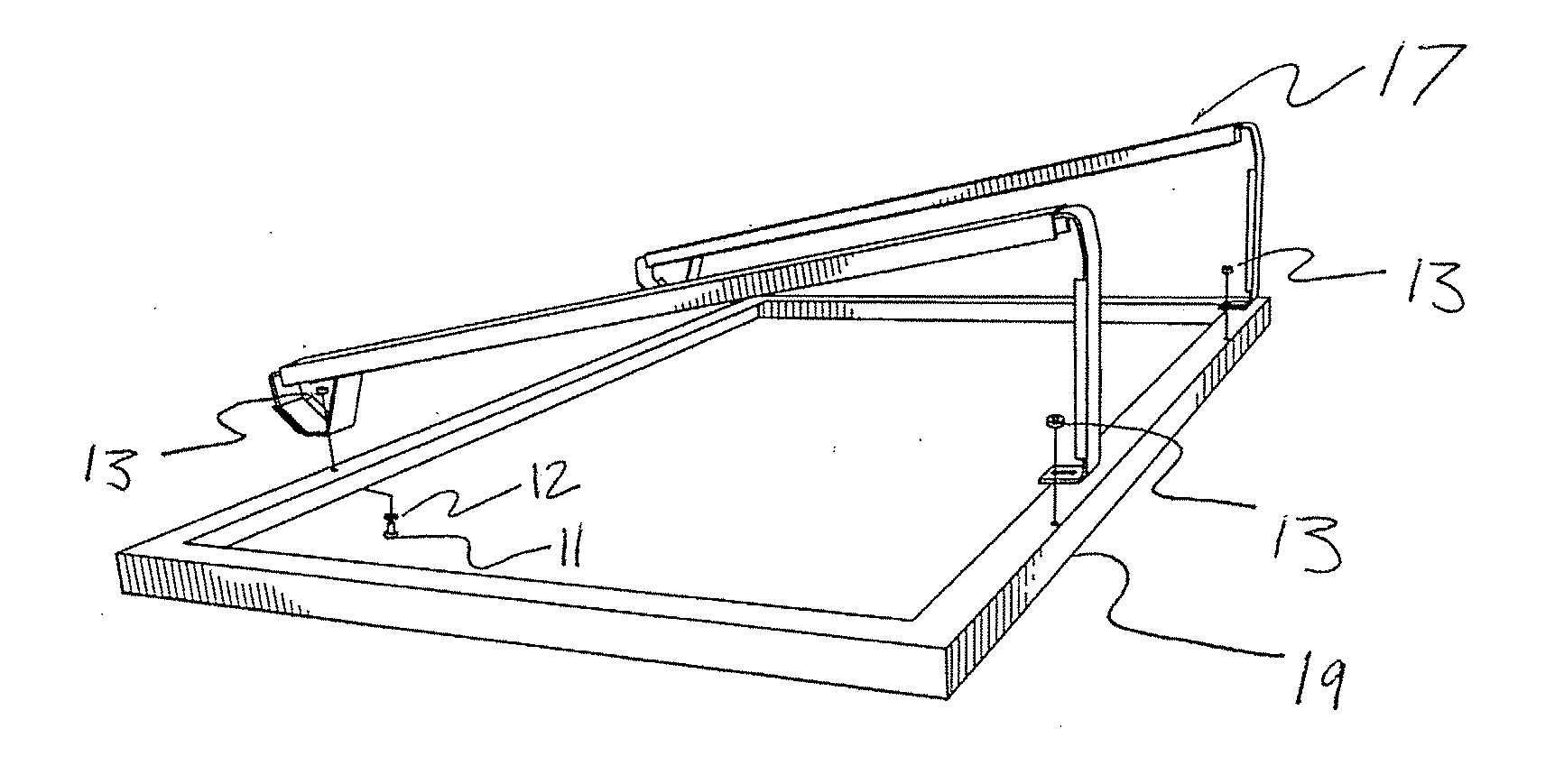
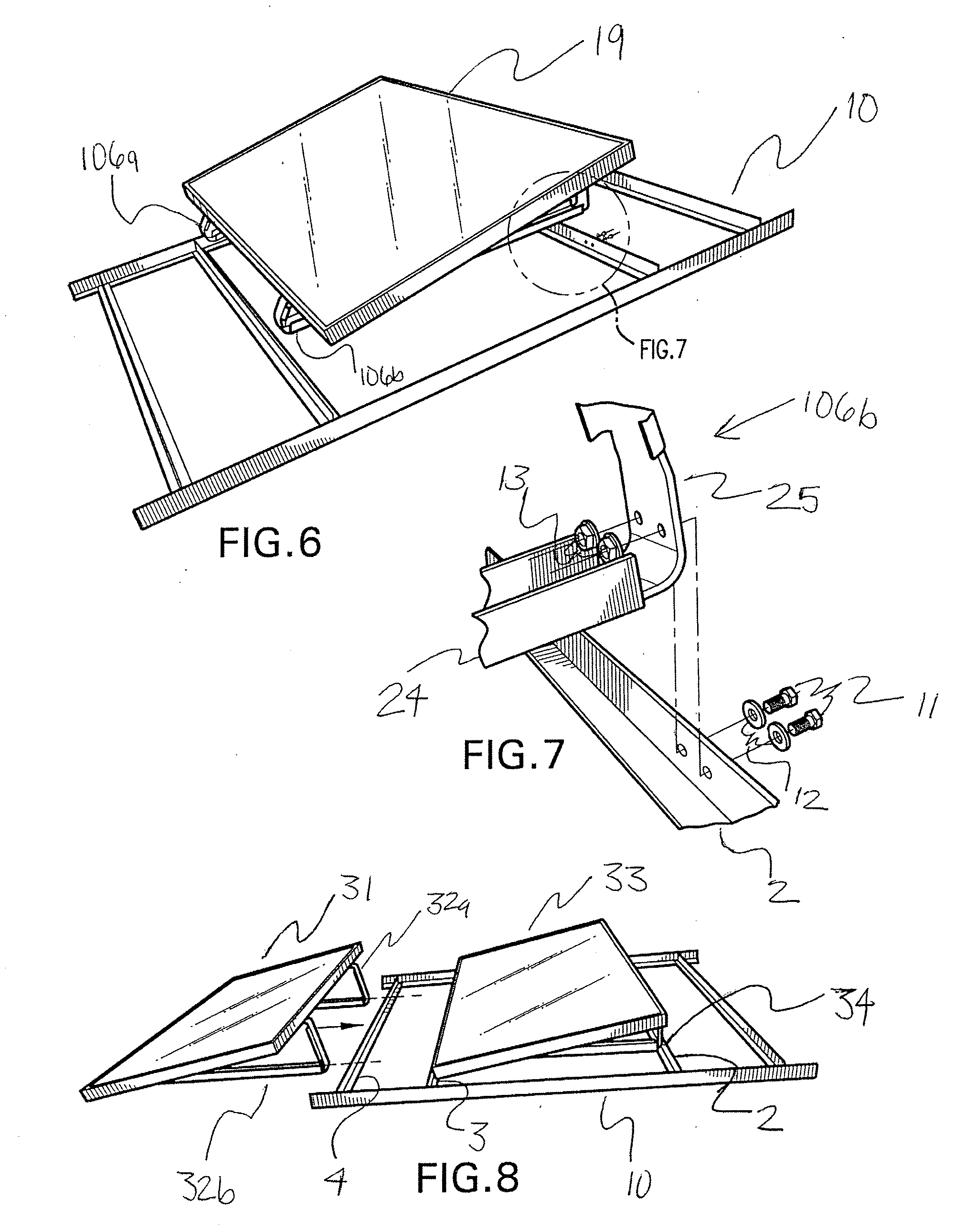
[0023]Embodiments consistent with the present invention utilize varying configurations of ballast frames to support PV modules for personal or residential energy needs. In particular, these ballast frames can be constructed to accommodate varying sizes of PV modules as well as more than one frame can be configured to attach to each other. Typically, the ballast frames are installed on roofing structures. Accordingly, weighted objects, e.g., concrete blocks, can be placed in ballast frames to combat natural lift forces, which can be created by wind.

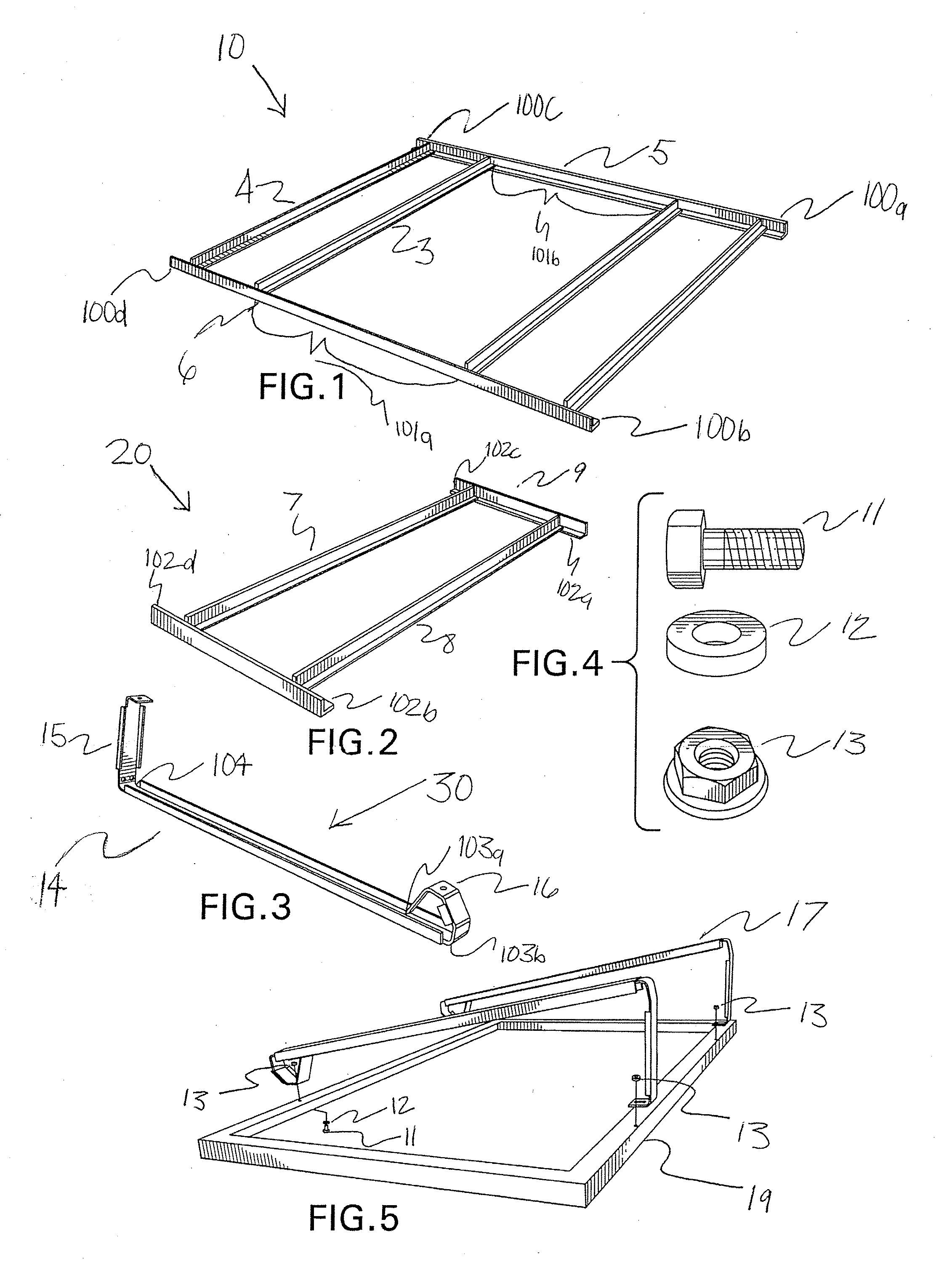
[0024]FIG. 1 is an exemplary non-limiting embodiment of double bay ballast frame 10. The double bay ballast frame 10 consists of horizontal members 1-4 and vertical connection members 5 and 6. Extensions 100a-d extend vertical connection members 5 and 6 for the purpose of connecting a plurality of ballast frame members. Extensions 100a and 100b are created by altering the position of horizontal members 1 and 2 within vertical members 5 and...


PUM


Abstract

A photovoltaic (PV) module mounting system comprises a plurality of PV modules, support brackets disposed under the modules and a ballast frame disposed under and attached to the support brackets. The ballast frame is supported on conventional building rooftops and attached thereto by conventional methods. The support bracket consists of front and rear supports, which can be adjusted to alter the desired tilt angles of the overlying PV modules. The ballast frames can be adjusted to varying widths and lengths. The system is effective in reducing the net effect of wind uplift force when modules are mounted on building rooftops. Additionally, the system provides the advantage of ease of use with less components and minimal roofing penetrations.

Description

RELATED APPLICATIONS[0001]This application claims priority under 35 U.S.C. § 119(e) to provisional application Ser. No. 60 / 996,486, filed Nov. 20, 2007, the contents of which are incorporated by reference.FIELD OF INVENTION[0002]The present invention is directed generally to an apparatus and methods for use in a removable or adjustable mounting or assembling photovoltaic (PV) ballast frame system for use on flat surfaces.BACKGROUND OF INVENTION[0003]Prior art PV module ballast frame structures typically has the disadvantage of having many parts and multiple penetrations to a roofing structure upon which it is installed. Accordingly, light weight components, minimal penetration, ease of installation and reduced labor costs are major concerns of customers in the PV module ballast frame market. Specifically, the number of penetrating roofing attachments can decrease the effectiveness of expensive roofing surfaces. As a result, there is an increasing need to develop PV mounting frame sy...

Claims


Application Information

Patent Timeline
Patent Type & Authority Applications(United States)
IPC IPC(8): A47B96/06
CPCF24J2/5233F24J2/5239F24J2/5245F24J2/5254F24J2002/5292H02S20/24Y02B10/20Y02E10/47Y02E10/50H02S20/00Y02B10/12F24S25/61F24S25/632F24S25/16F24S25/13F24S2025/02Y02B10/10
Inventor MEIER, CHRIS M.RHODES, COLLIN J.
Owner UNIRAC INC
Why Eureka
Try Eureka