Reciprocating seal

a technology of reciprocating seals and sealing plates, applied in the direction of engine seals, springs/dampers, shock absorbers, etc., can solve the problems of difficult to improve the characteristics of frictional force, and achieve the effect of preventing an increase in frictional for

Inactive Publication Date: 2009-05-28
NOK CORP
View PDF6 Cites 4 Cited by
  • Summary
  • Abstract
  • Description
  • Claims
  • Application Information

AI Technical Summary

Benefits of technology

[0028]According to the construction of the invention, the seal lip has the two-step lip structure and hence the position of the seal lip can be stabilized.
[0030]Further, since the plurality of protrusions are formed on the surface of the lip of the second step, they can prevent an increase in the frictional force.

Problems solved by technology

As described above, in the case of a conventional art, it is difficult to improve frictional force characteristics and, at the same time, to improve sealing performance.

Method used


Image

  • Reciprocating seal
  • Reciprocating seal
  • Reciprocating seal

Examples


Embodiment Construction

[0035]Hereafter, the best mode of this invention will be described as an example in detail with reference to the drawings. However, as for the size, material, shape, and relative arrangement of constituent parts described in this embodiment, it is not intended to limit the scope of this invention only to these unless otherwise specified.

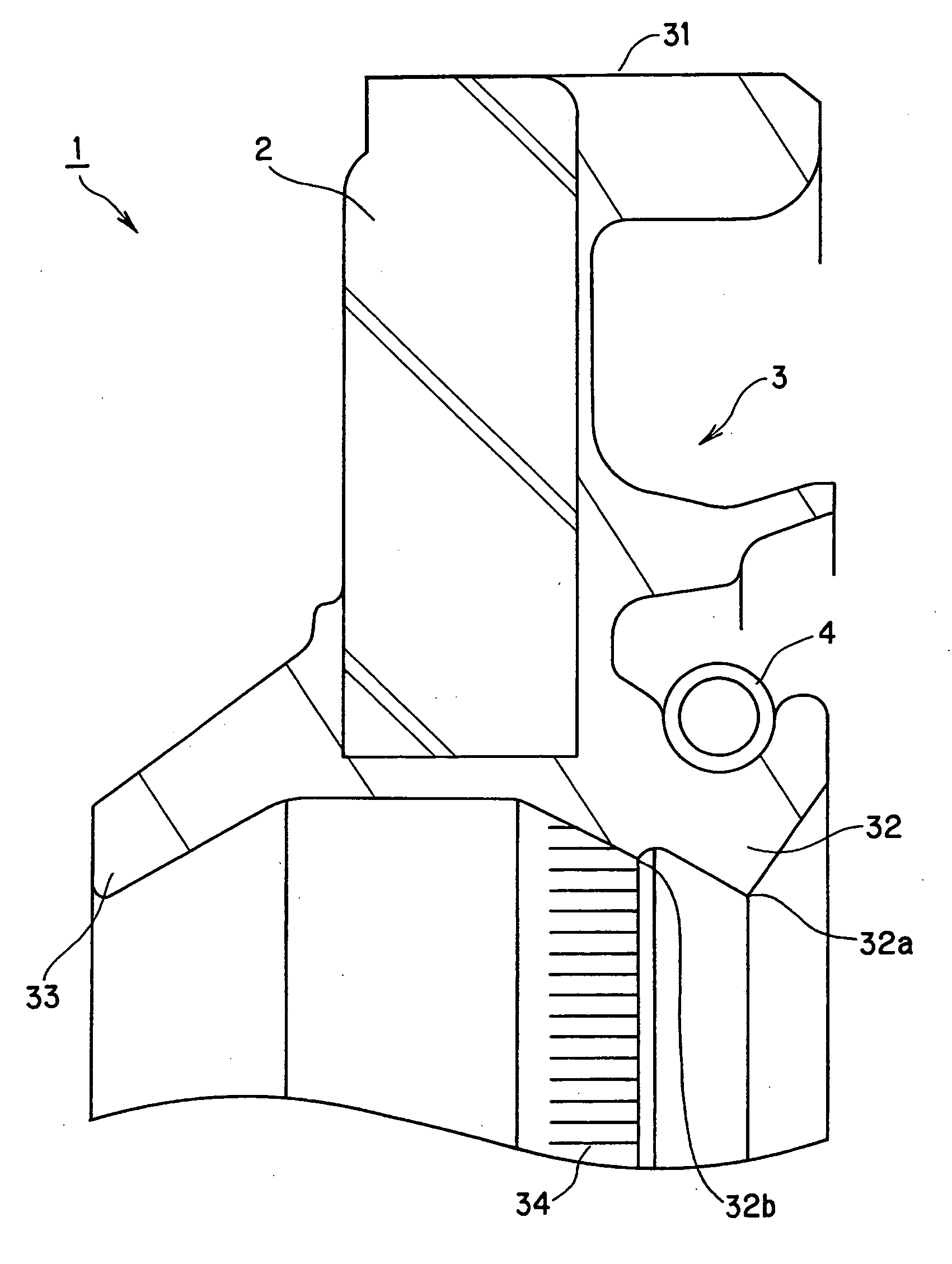
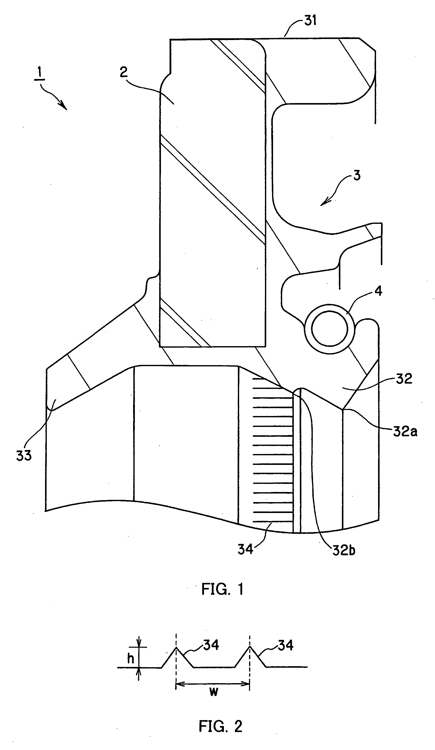
[0036]A reciprocating seal according to the invention will be described with reference to FIG. 1.

[0037]FIG. 1 is a schematic sectional view of a reciprocating seal according to the embodiment of the invention.

[0038]The reciprocating seal 1 according to the embodiment of the invention can be suitably used for a shock absorber mounted in an automobile and the like.

[0039]Further, the reciprocating seal 1 according to the embodiment of the invention is arranged in an annular space between a shaft (not shown) and the inner periphery of a housing (shaft hole made in the housing, in more detail), which move relatively to each other in the direction of the s...


PUM


Abstract

The present invention relates to a reciprocating seal used, for example, for a shock absorber. A main seal lip 32 has a two-step lip structure including a first lip 32a and a second lip 32b and a plurality of protrusions 34 extending in the direction of the shaft are formed on a sliding contact surface of the second lip 32b, thereby improving frictional force characteristics and, at the same time, improving sealing performance.

Description

TECHNICAL FIELD[0001]The present invention relates to a reciprocating seal used, for example, for a shock absorber.BACKGROUND ART[0002]A reciprocating seal of this kind has been conventionally known that is used for a shock absorber mounted in an automobile and the like.[0003]Among reciprocating seals according to a conventional art like this is, for example, a seal shown in FIG. 3.[0004]FIG. 3 is a schematic sectional view of a reciprocating seal according to a conventional art.[0005]The reciprocating seal is arranged in an annular space between a shaft (not shown) and the inner periphery of a housing (in more detail, shaft hole made in the housing), which move relatively in the direction of the shaft, to form a sealed space.[0006]A reciprocating seal 100 according to the conventional art, as shown in the drawing, is mainly provided with a metal ring 200 and a rubber seal 300 baked on the metal ring 200.[0007]The rubber seal 300 has an outer peripheral seal portion 301 mounted on t...

Claims


Application Information

Patent Timeline
Patent Type & Authority Applications(United States)
IPC IPC(8): F16J15/32F16F9/36F16J15/3232F16J15/56
CPCF16F9/36F16J15/56F16J15/3236F16J15/3232F16J15/32
Inventor ARAI, HIDENORITAKENO, KAZUKIYAMANE, ICHIROMUNEKATA, SHINOBUYAMASHINA, KATSUMIWATANABE, MASARU
Owner NOK CORP
Why Eureka
Try Eureka