Phase current sampling and regulating apparatus and methods, and electric motor drive systems

US20090134833A1Inactive Publication Date: 2009-05-28GM GLOBAL TECH OPERATIONS LLC

Image

  • Phase current sampling and regulating apparatus and methods, and electric motor drive systems
  • Phase current sampling and regulating apparatus and methods, and electric motor drive systems
  • Phase current sampling and regulating apparatus and methods, and electric motor drive systems

Examples


Embodiment Construction

[0023]The following detailed description is merely exemplary in nature and is not intended to limit the inventive subject matter or the application and uses of the inventive subject matter. Furthermore, there is no intention to be bound by any expressed or implied theory presented in the preceding technical field, background, brief summary or the following detailed description.

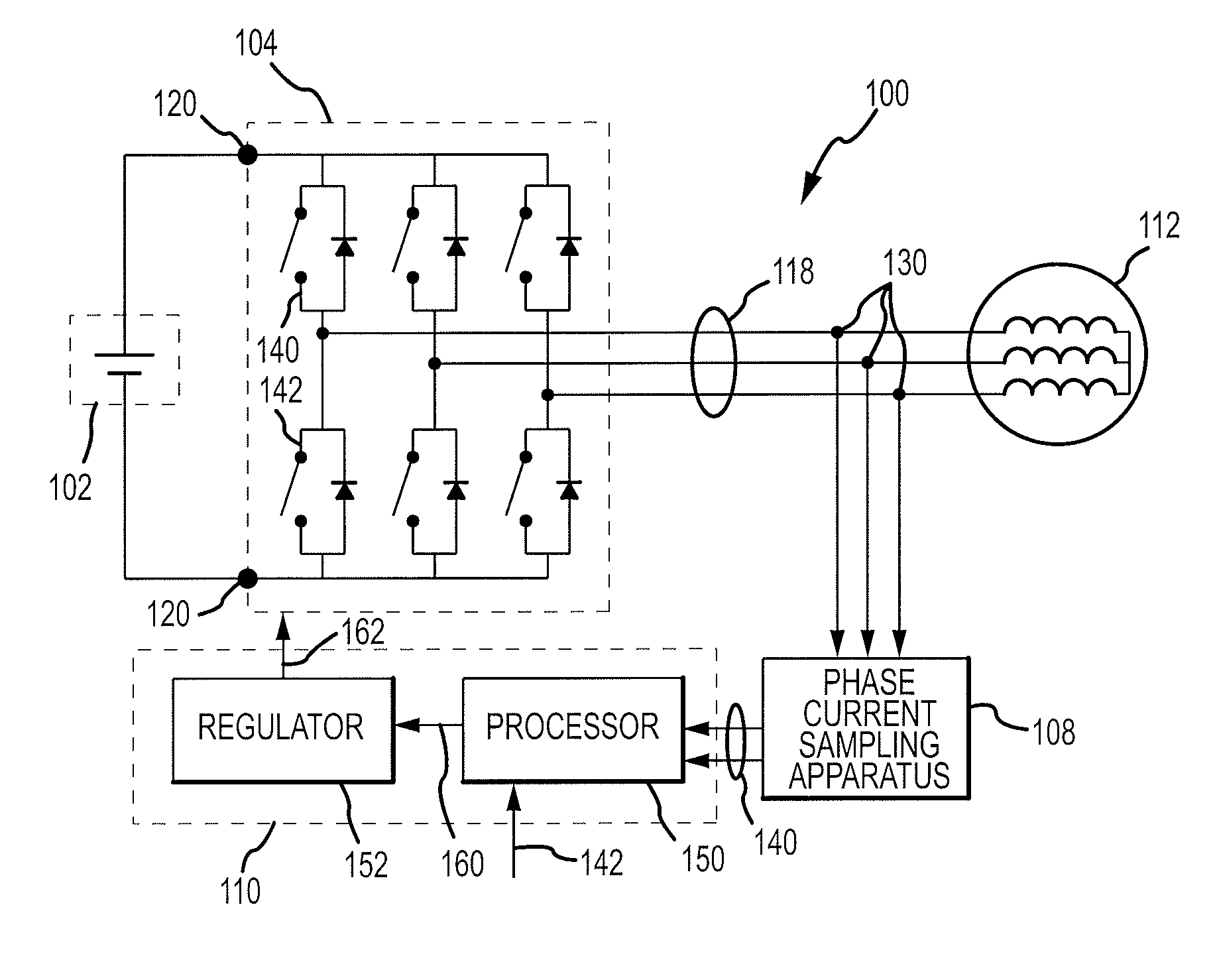
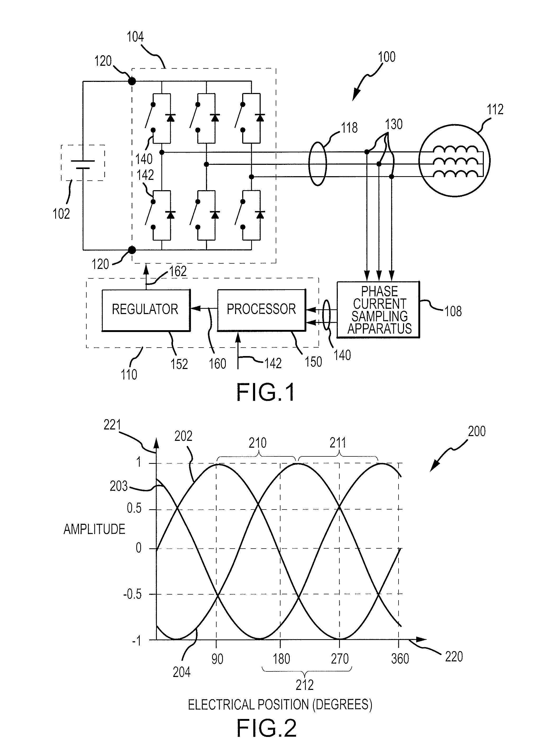
[0024]FIG. 1 illustrates a simplified schematic diagram of an electric motor drive system 100, in accordance with an example embodiment of the inventive subject matter. System 100 includes a power source 102, an inverter 104, a phase current sampling apparatus 108, and a controller 110, which are adapted to drive an electric motor 112, in an embodiment. As will be described in more detail below, electric motor drive system 100 is adapted to induce multiple phase current waveforms 118, to sample and analyze the multiple phase current waveforms 118, and to control generation of the phase current waveforms 118 ba...


PUM


Abstract

In various embodiments, a phase current sampling apparatus (300, 600, FIGS. 3, 6), an electric motor drive system (100, FIG. 1), and a motor vehicle (1200, FIG. 12) include switching circuitry adapted to receive first and second phase current waveforms. The switching circuitry provides the first phase current waveform during at least two offset sampling instants, and provides the second phase current waveform during a reference sampling instant. An analog-to-digital converter is adapted to sample the first phase current waveform at the offset sampling instants, and to sample the second phase current waveform at the reference sampling instant. An embodiment of a method for regulating phase current waveforms includes an analog-to-digital converter generating samples of a first phase current waveform at sampling instants that occur before and after a reference sampling instant, and generating a sample of a second phase current waveform at the reference sampling instant.

Description

TECHNICAL FIELD[0001]The inventive subject matter generally relates to apparatus and methods for sampling phase currents, and more particularly relates to such apparatus and methods incorporated into electric motor drive systems.BACKGROUND[0002]Electric drives are used to control the phase currents of electric motors. In a digitally-controlled system, multiple phase currents typically are sampled simultaneously and converted into digital values using analog-to-digital (A-to-D) converters. These digital values are provided to a system controller, which may adjust the phase currents according to the digital values.[0003]In some systems, multiple analog-to-digital (A-to-D) converters may be used simultaneously to sample the multiple phase currents. For example, in a system which provides three-phase current, three A-to-D converters may be implemented in parallel sampling channels. The sampling instants for each phase current typically are controlled with precision, which may enable det...

Claims


Application Information

Patent Timeline
28 May 2009
Publication
US20090134833A1
IPC
H02P27/00; G05F1/12; H03K3/02
CPC
G01R19/2509; H02P21/00; G01R31/007; G01R19/2513
Inventors
WEST, STEPHEN T.; WELCHKO, BRIAN A.