Turbocharger with at least one variable turbine geometry turbine

Inactive Publication Date: 2009-05-28
BOSCH MAHLE TURBO SYST GMBH & CO KG
View PDF15 Cites 12 Cited by
  • Summary
  • Abstract
  • Description
  • Claims
  • Application Information

AI Technical Summary

Benefits of technology

[0005]To reduce the number of rotating/pivoting parts for varying the turbine geometry, it is provided that the vanes be immovably fixed to the vane support, and exhibit varying angular settings relative to the rotor disk in different sectors of the circumferential area, wherein the turbine for sector selection exhibits a cover device that can turn relative to the vane support and has at least one opening in its jacket surface. The opening here preferably extends from the inner circumference to the outer circumference of the cover device. The angular setting for the used vanes is selected through sector selection via the opening in the cover device, which releases the select

Problems solved by technology

To ensure that the vanes can be adjusted in the entire temperature range of the exhaust gas stream, high requirements must be placed on the fit of the bearing devices of the vanes, which in turn is associated with high manufacturing costs.
The gap between the vanes and a casing of the turbine brought about by the principle of pivoting capability additionally provide for secondary flows, and hence losses in efficiency.
In addition, soot may build up in the gaps, thereby blocking the adjustment mechanism.
All efforts notwithstanding, conventional VTG tu

Method used


Image

  • Turbocharger with at least one variable turbine geometry turbine
  • Turbocharger with at least one variable turbine geometry turbine
  • Turbocharger with at least one variable turbine geometry turbine

Examples


Example

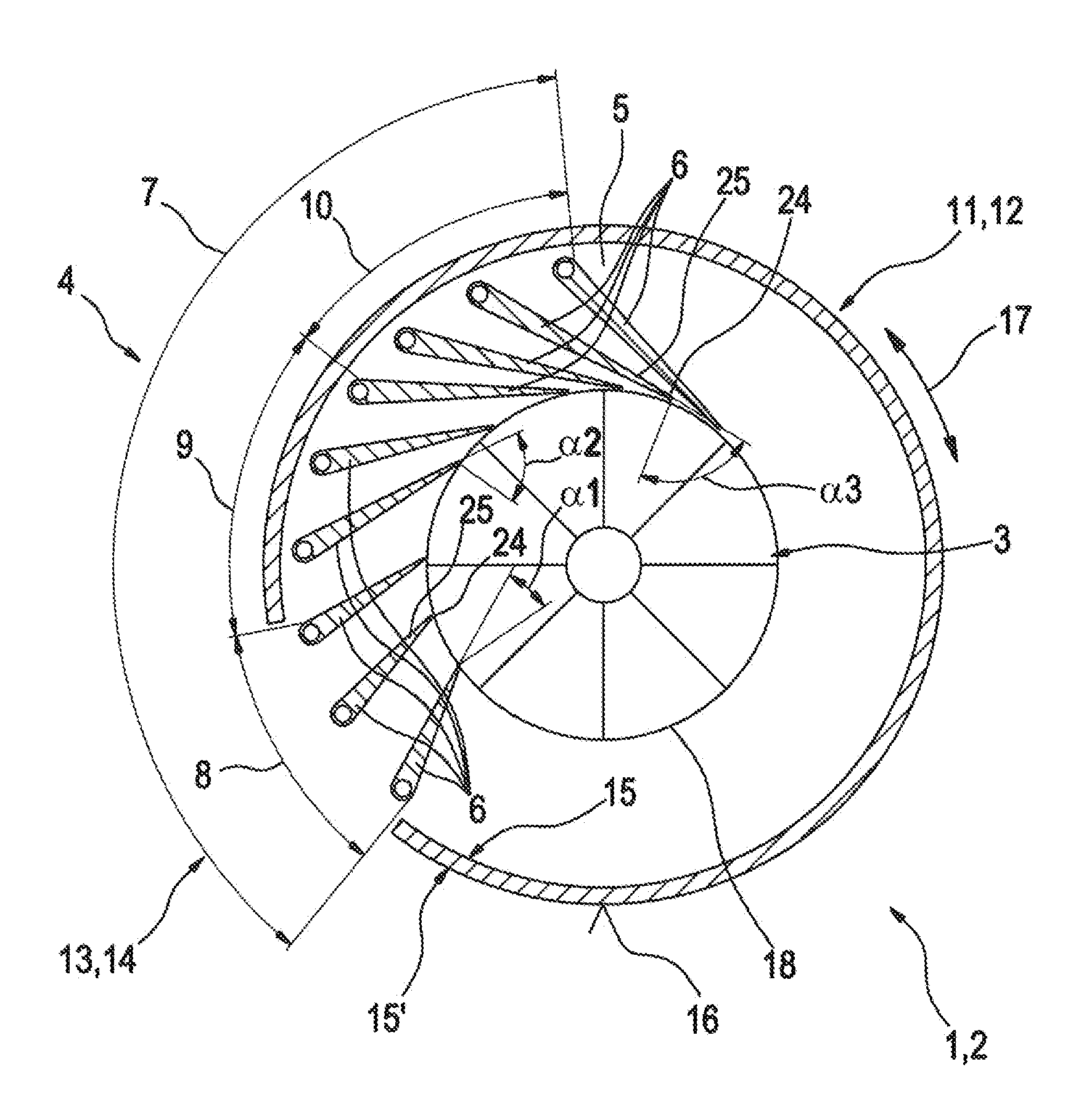
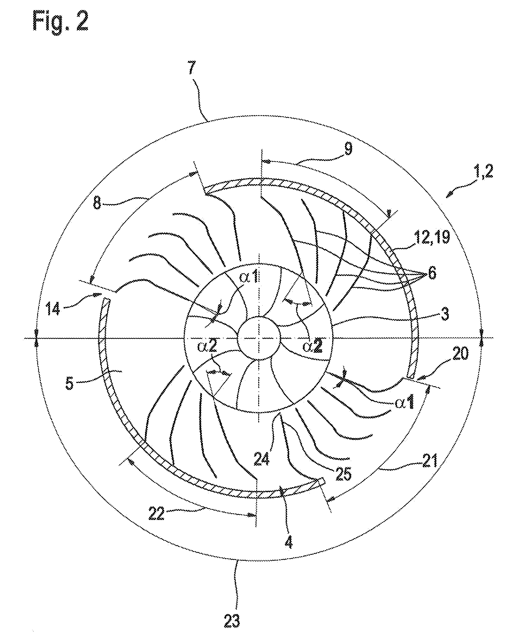
[0017]FIG. 1 shows a turbine 2 of a combustion engine turbocharger, which is designed as a radial turbine 1, and exhibits variable turbine geometry. A vane ring 4 is arranged around a rotor disk 3 of the turbine 2, which is formed by vanes 6 spaced apart from each other. FIG. 1 shows only one circumferential area 7 of the vane ring 4. The vane ring 4 is divided into several sectors 8, 9, 10, of which only three sectors 8, 9, 10 are shown in the circumferential area 7 depicted on FIG. 1. The vanes 6 of each sector 8, 9, 10 exhibit a uniform angular setting α1, α2, α3 relative to the respective radial extension of the rotor disk 3. The first sector 8 has a first angular setting α1, the second sector 9 a second angular setting α2, and the third sector 10 a third angular setting α3. The number of vanes 6 is identical for each sector 8, 9, 10.

[0018]A cover device 12 designed as a sleeve 11 with an opening 14 designed as a recess 13 is arranged around the vane ring 4, The opening 14 exten...


PUM


Abstract

The invention relates to a turbocharger for a combustion engine, in particular of a motor vehicle, with at least one variable turbine geometry turbine, which exhibits a rotor disk and vanes arranged on a vane support, which are spaced apart from each other around the rotor disk in at least one circumferential area, and with an adjuster to select the angular setting of the vanes. It is provided that the vanes (6) are fixed securely to the vane support (5), and exhibit different angular settings (α1, α2, α3) relative to the rotor disk (3) in varying sectors (8, 9, 10) of the circumferential area (7), wherein the turbine (2) exhibits a cover device (12) that can rotate relative to the vane support (5) with at least one opening (14, 20) in its jacket surface (16) for purposes of sector selection.

Description

[0001]The invention relates to a turbocharger for a combustion engine, in particular of a motor vehicle, with at least one variable turbine geometry turbine, which exhibits a rotor disk and vanes arranged on a vane support, which are spaced apart from each other around the rotor disk in at least one circumferential area.PRIOR ART[0002]A turbocharger with at least one variable turbine geometry-turbine (VTG-turbine) is known in the art. To this end, the turbine designed as a radial turbine exhibits an annular array of vanes spaced apart from each other and arranged concentrically around the rotor disk, which are arranged on a vane support. These vanes are responsible for guiding the flow on the rotor disk. The vanes are arranged on the vane support so that they can pivot around bearing arrangements and are swiveled by an adjuster for selecting the angular setting of the vanes. The angular setting of the vane supports relative to a flowing direction of an exhaust gas stream driving the...

Claims


Application Information

Patent Timeline
IPC IPC(8): F01D17/16
CPCF01D17/165F05D2220/40F02C6/12
Inventor LAUBENDER, JOCHENSTEIDTEN, THOMASRAUSCHER, MARTIN
Owner BOSCH MAHLE TURBO SYST GMBH & CO KG
Why Eureka
Try Eureka