Low-frequency flight control system oscillatory faults prevention via horizontal and vertical tail load monitors

Active Publication Date: 2009-05-28
YABORA IND AERONAUTICA SA
View PDF21 Cites 14 Cited by
  • Summary
  • Abstract
  • Description
  • Claims
  • Application Information

AI Technical Summary

Benefits of technology

[0004]An aircraft pilot adjusts the position (orientation) of surfaces such as rudders and elevators so as to control the aircraft's flight. In traditional aircraft designs, cables and other mechanical components directly link the control stick to the surfaces, usually with the help of actuators. Modern aircraft designs, on the other hand, feature complex electronic components within their Flight Control Systems, thereby introducing new variables and data processing platforms (computers, electronic circuitry) in the control loop absent from purely mechanical Flight Control Systems. At the same time that many new and useful functionalities are brought on, a more complex Flight Control System presents i

Problems solved by technology

Modern aircraft designs, on the other hand, feature complex electronic components within their Flight Control Systems, thereby introducing new variables and data processing platforms (computers, electronic circuitry) in the control loop absent from purely mechanical Flight Control Systems.
At the same time that many new and useful functionalities are brought on, a more complex Flight Control System presents itself with the possibility of containing several distinctive sources of faulty behavior—such as, for example, wrong oscillatory inputs coming from a malfunctioning Flight Control Computer and sent to the control surfaces.
Faulty persistent surface (e.g. rudder and/or elevator) oscillations while an aircraft is in air, when not correctly detected, may lead to structural damage due to cumulative loads that can exceed the aircraft designed oscillatory envelope and, eventually, may result in catastrophic events, especially in those cases when limit loads are repeatedly reached.
In other words, under such persistent oscillations, control surfaces can permanently deform, crack or even snap off the aircraft.
However, for low frequencies,

Method used


Image

  • Low-frequency flight control system oscillatory faults prevention via horizontal and vertical tail load monitors
  • Low-frequency flight control system oscillatory faults prevention via horizontal and vertical tail load monitors
  • Low-frequency flight control system oscillatory faults prevention via horizontal and vertical tail load monitors

Examples


Embodiment Construction

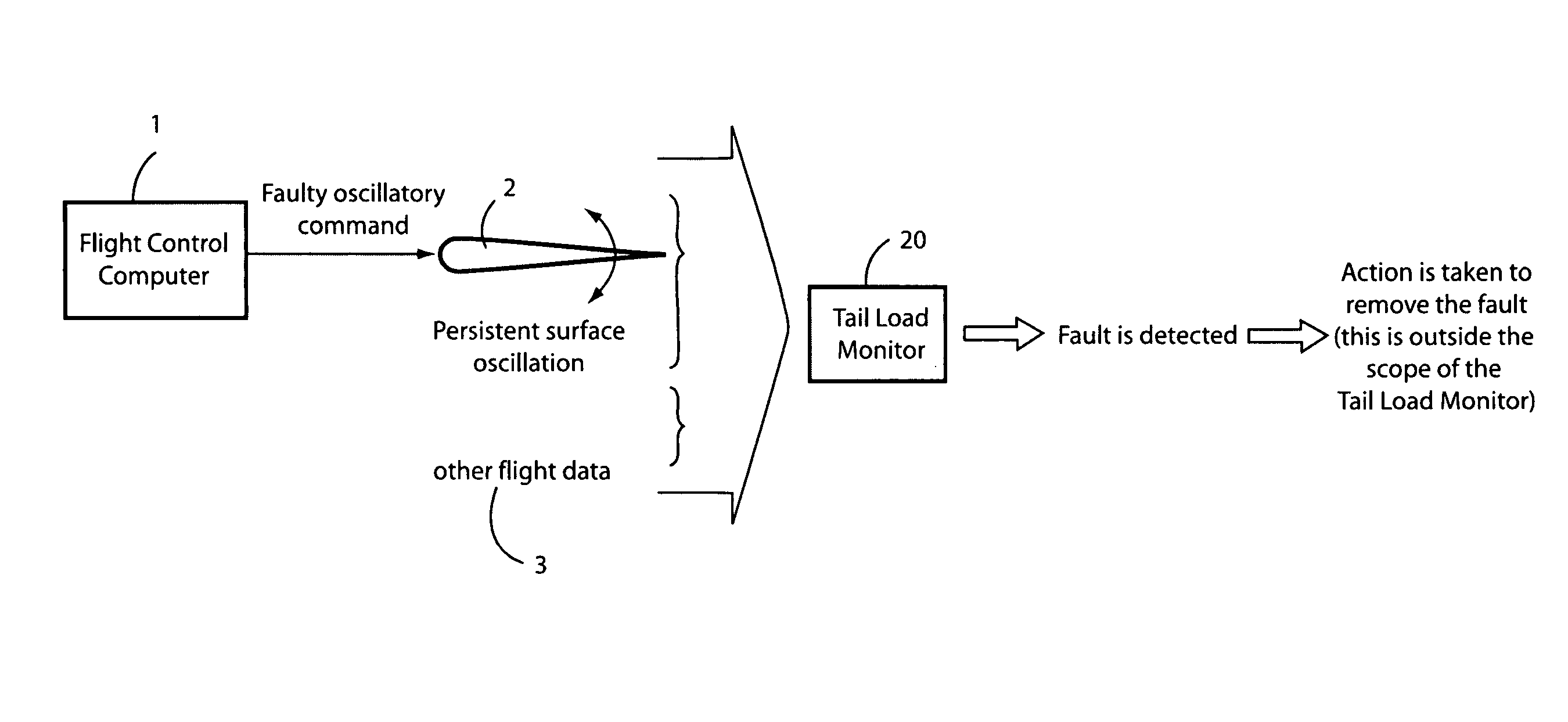
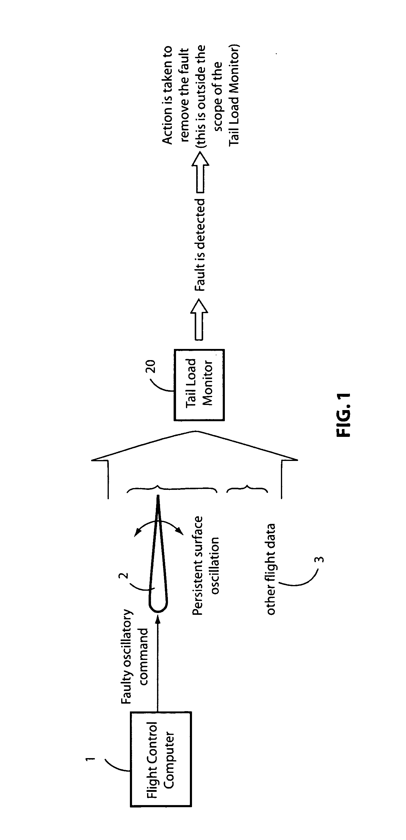
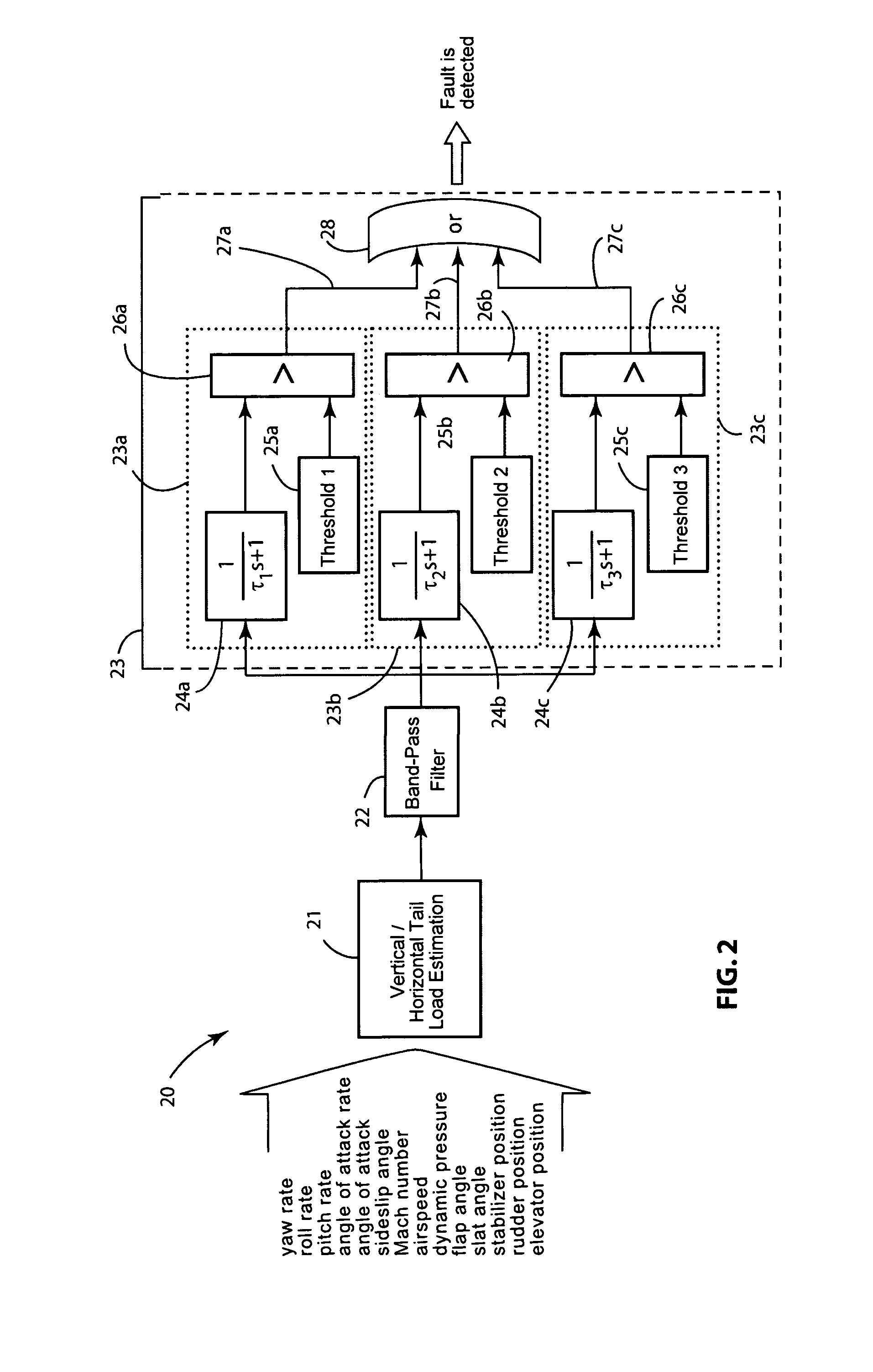
[0016]There are two kinds of tail load monitoring activities: one related to the vertical tail and one related to the horizontal tail. Therefore, the exemplary illustrative non-limiting Tail Load Monitoring System 20 as shown in FIG. 1 can be either a Vertical Tail Load Monitor or a Horizontal Tail Load Monitor. In other words, both Vertical and Horizontal Tail Load Monitors share the same basic exemplary illustrative non-limiting architecture, an implementation of which is illustrated in FIG. 2.

[0017]Their mitigation effects scope comprises, respectively, unwanted persistent rudder and elevator oscillations (that may result, for example, from simultaneous faults in multiple lanes of a digital processing unit such as the one depicted in FIG. 1), that exceed the designed oscillatory envelope for low frequencies.

[0018]The exemplary illustrative non-limiting Vertical and Horizontal Tail Load Monitors thus protect the aircraft from structural damage that can arise as a consequence of co...


PUM


Abstract

The Tail Load Monitoring System detects faulty low frequency (e.g. those in the range from 0.1 to 1 Hz) oscillatory conditions caused by Flight Control System malfunctions while the aircraft is in air by means of a continuous assessment of the estimated tail load behavior and data processing. Both estimation and data processing activities are provided by a dedicated architecture featuring a tail load estimation module, a band-pass filter and three independent paths that continuously monitor nuisance fault detection events avoidance, catastrophic events avoidance (addressing a limit load criterion), and structural damage avoidance (addressing fatigue life criteria).

Description

CROSS-REFERENCES TO RELATED APPLICATIONS[0001]None.STATEMENT REGARDING FEDERALLY SPONSORED RESEARCH OR DEVELOPMENT[0002]None.TECHNICAL FIELD[0003]The technology herein relates to a new concept for detecting low frequency persistent oscillatory signals generated by a Flight Control System malfunction that causes faulty persistent aircraft surface oscillations, namely the Tail Load Monitoring Concept.BACKGROUND AND SUMMARY[0004]An aircraft pilot adjusts the position (orientation) of surfaces such as rudders and elevators so as to control the aircraft's flight. In traditional aircraft designs, cables and other mechanical components directly link the control stick to the surfaces, usually with the help of actuators. Modern aircraft designs, on the other hand, feature complex electronic components within their Flight Control Systems, thereby introducing new variables and data processing platforms (computers, electronic circuitry) in the control loop absent from purely mechanical Flight C...

Claims


Application Information

Patent Timeline
IPC IPC(8): B64C19/00
CPCG05D1/0825
Inventor GRINITS, ERICK VILEDE OLIVEIRA ALVES JUNIOR, MARCO ANTONIOGANGSAAS, DAGFINNNEGRAO, ROBERTO GARCIATROTTA, BIANCA PRAZIMSILVA, FABIANO PRIETOFILHO, MAURICIO MARTINS DE ALMEIDACOCCOLIN, MARCO ANTONIOGARCIA, KARINA SANCHESCARMONA DE CAMPOS, DANIELSARACHO, CRISTINA MINIOLIMOREIRA, FERNANDO JOSE DE OLIVEIRA
Owner YABORA IND AERONAUTICA SA
Why Eureka
Try Eureka