
Casting Apparatus and Method

a technology of casting apparatus and casting method, which is applied in the direction of coating, molten spray coating, metallic material coating process, etc., can solve the problems of affecting the formation of large diameter preforms, affecting the quality of metal alloy casting, and unavoidable byproducts of spray forming, so as to reduce the amount of spray droplets, prevent overspray accumulation, and prevent the effect of forming

Active Publication Date: 2009-06-04
ATI PROPERTIES
View PDF89 Cites 30 Cited by
  • Summary
  • Abstract
  • Description
  • Claims
  • Application Information

AI Technical Summary

Benefits of technology

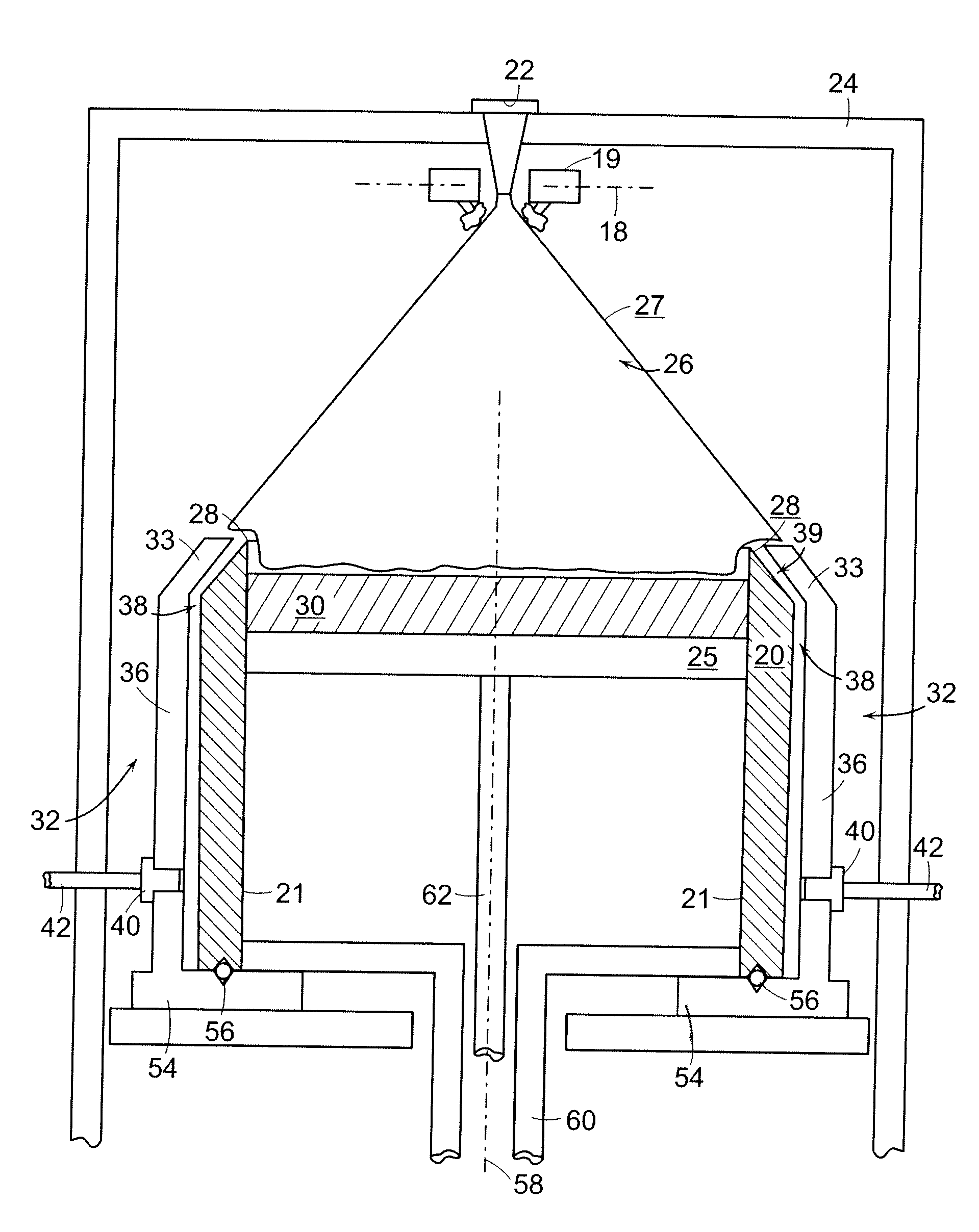
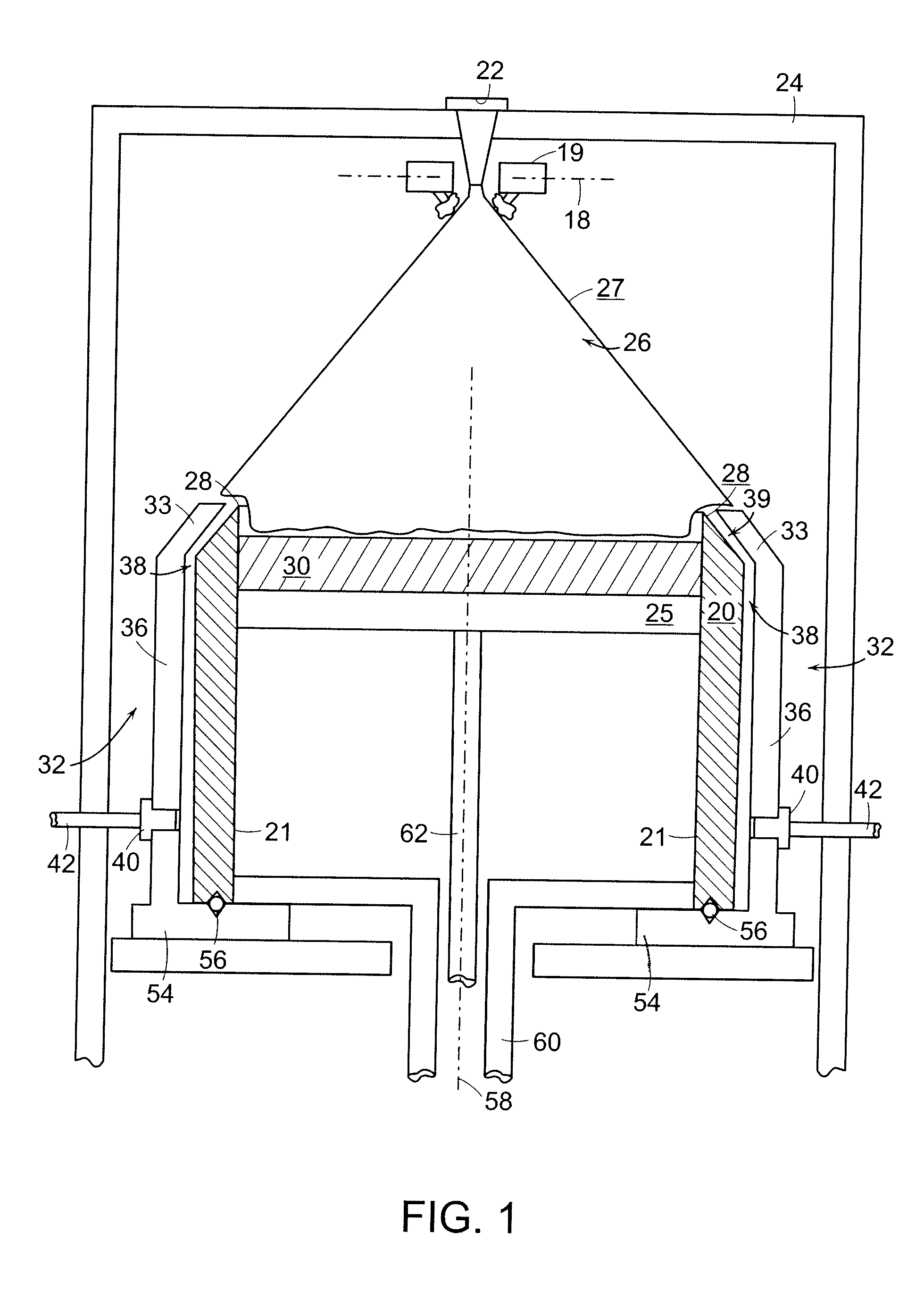
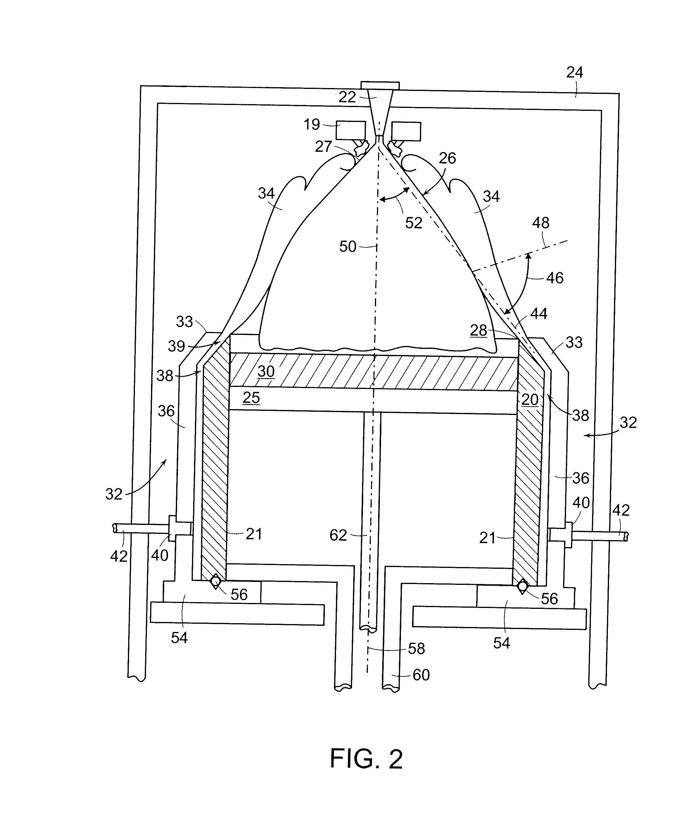
[0006]In one form of the invention, a nucleated casting apparatus can include an atomizing nozzle configured to produce a droplet spray of a metallic material, a mold configured to receive the droplet spray and form a preform therein, and a gas injector which can limit, and possibly prevent, overspray from accumulating on the mold. In various embodiments, the gas injector can be configured to produce a gas flow which can impinge on the droplet spray to redirect the droplet spray away from a side wall of the mold. In at least one such embodiment, the gas flow can push the droplet spray into the mold, thereby reducing the amount of the droplet spray which accumulates on top of the side wall. In various embodiments, the droplet spray may be directed by the atomizing nozzle in a generally downward direction, whereas the gas flow may be directed in a generally upward direction such that the gas flow forms a physical barrier, ‘curtain’, or ‘fence’ surrounding the perimeter of the mold and biases the droplet spray to a preferred path.

Problems solved by technology

Spray forming, however, suffers from a number of disadvantages that make its application to the formation of large diameter preforms problematic.
Furthermore, an unavoidable byproduct of spray forming is overspray, wherein a portion of the metal spray misses the developing preform altogether or solidifies in flight without attaching to the preform.
In these circumstances, the nucleated casting process may have to be stopped in order to remove the overspray, and this may result in scrapping the preform.
Accordingly, there are drawbacks associated with certain known techniques in which preforms are cast from a droplet spray.

Method used


Image

  • Casting Apparatus and Method
  • Casting Apparatus and Method
  • Casting Apparatus and Method

Examples


example 1

Evaluation of Gas Injector Gap Configuration

[0038]Referring to FIG. 9, various test samples, i.e., Test Samples A-D and F, were utilized to re-direct a droplet spray of molten metallic material as described above. The test samples were then examined to compare the ability of gas injectors having different configurations to reduce the adhesion or accumulation of overspray onto the test samples. Test Sample A, referring to FIGS. 9 and 10, included a coupon which was configured to simulate at least a portion of a mold side wall and a gas injector as outlined above. Test Sample A included a vertical surface (demarcated “A” in FIG. 10), a top surface, a gap positioned intermediate the vertical surface and the top surface, and a plenum configured to place a source of inert gas in fluid communication with the gap. As depicted in FIG. 9, the gap included an axis oriented at a 60 degree angle with respect to the horizontal, i.e., at a 30 degree angle with respect to an axis of the droplet sp...

example 2

Further Evaluation of Gas Injector Gap Configuration

[0042]Referring to FIG. 17, various additional test samples, i.e., Test Samples G, H, and J, were also utilized to re-direct a droplet spray of molten metallic material. Similar to the above, the test samples were then examined to compare the ability of the gas injectors to reduce the adhesion or accumulation of overspray onto the test samples. Test Sample G, H, and J, similar to Test Samples A-D and F, each included a coupon which was configured to simulate at least a portion of a mold side wall and a gas injector. As depicted in FIG. 17, the gas injector of Test Sample G included a gap having an axis oriented at an approximately 60 degree angle with respect to the horizontal, i.e., at an approximately 30 degree angle with respect to an axis of the droplet spray. As also depicted in FIG. 17, Test Sample H included a gap having an approximately 45 degree axis and Test Sample J included a gap having an approximately 67 degree axis.

[...

example 3

Evaluation of Inert Gas Pressure

[0045]Referring to FIG. 13, various specimens of Test Sample A were utilized to re-direct a droplet spray of molten metallic material as described above. The test samples were then examined to compare the ability of various gas injectors having substantially the same configuration, but supplied with inert gas flows having different pressures, to reduce the adhesion or accumulation of overspray onto the test samples. In the first example, depicted in FIG. 13(a), nitrogen gas having a pressure of approximately 0.2 bar was supplied to the test sample. In the second example, depicted in FIG. 13(b), nitrogen gas having a pressure of approximately 1.0-1.2 bar was supplied to the second test sample and, in the third example, depicted in FIG. 13(c), nitrogen gas having a pressure of approximately 2-3 bar was supplied to the third test sample. As illustrated in FIG. 13, it was observed that less overspray accumulated on the third test sample (2-3 bar) than on ...


PUM

PropertyMeasurementUnit
surface roughnessaaaaaaaaaa
angleaaaaaaaaaa
angleaaaaaaaaaa

Abstract

A nucleated casting apparatus including an atomizing nozzle configured to produce a droplet spray of a metallic material, a mold configured to receive the droplet spray and form a preform therein, and a gas injector which can limit, and possibly prevent, overspray from accumulating on the mold. The gas injector can be configured to produce a gas flow which can impinge on the droplet spray to redirect at least a portion of the droplet spray away from a side wall of the mold. In various embodiments, the droplet spray may be directed by the atomizing nozzle in a generally downward direction and the gas flow may be directed in a generally upward direction such that the gas flow circumscribes the perimeter of the mold.

Description

STATEMENT REGARDING FEDERALLY SPONSORED RESEARCH OR DEVELOPMENT[0001]Certain of the research leading to the present invention was funded by the National Institute of Standards and Technology Advanced Technology Program (NIST ATP), Contract No. 70NANB1H3042. The United States may have certain rights in the invention.CROSS REFERENCE TO RELATED APPLICATIONS[0002]Not applicable.TECHNICAL FIELD AND INDUSTRIAL APPLICABILITY OF THE INVENTION[0003]The present invention relates to an apparatus and a method for casting metal and metal alloys. The present invention is also directed to preforms and other articles produced by the method and / or apparatus of the present invention.DESCRIPTION OF THE INVENTION BACKGROUND[0004]In certain applications, components must be manufactured from large diameter metal or metal alloy preforms which are substantially free of defects. (For ease of reference, the term “metallic material” is used herein to refer collectively to unalloyed metals and to metal alloys....

Claims


Application Information

Patent Timeline
Patent Type & Authority Applications(United States)
IPC IPC(8): B22D23/00B22D27/15B22D1/00
CPCC23C4/121B22D23/003C23C4/123
Inventor FORBES JONES, ROBIN M.SHAFFER, STERRY A.
Owner ATI PROPERTIES
Learn More