Material placement method and apparatus

a material and placement method technology, applied in the field of aerodynamic aircraft parts and structural parts, can solve the problems of affecting the material application process, challenging or sometimes impossible to achieve, and achieve the effect of effectively dispensed and compacting the material

Inactive Publication Date: 2009-06-04
SPIRIT AEROSYSTEMS
View PDF6 Cites 20 Cited by
  • Summary
  • Abstract
  • Description
  • Claims
  • Application Information

AI Technical Summary

Benefits of technology

[0010]The compacting roller of each roller assembly may be substantially crowned along its outer circumferential surface to more effectively dispense and compact the material to the surface. The compacting roller may be made of a malleable material such as rubber, allowing the crowned surface to compress against the surface as pressure is applied to the roller.

Problems solved by technology

Because of the many thousands of strands required for a typical composite part, this retract-rotate-reapproach method can add a significant amount of time to the material application process.
This can be challenging or sometimes impossible to achieve depending on the complexity of the contours required for a given part.

Method used


Image

  • Material placement method and apparatus
  • Material placement method and apparatus
  • Material placement method and apparatus

Examples


Embodiment Construction

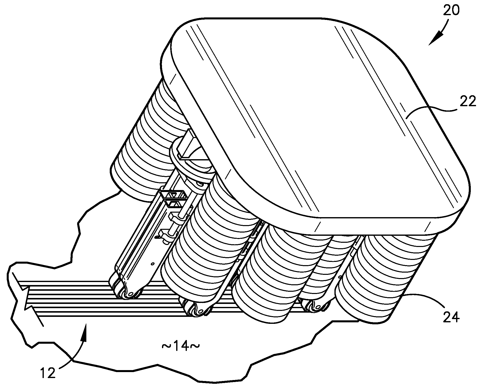
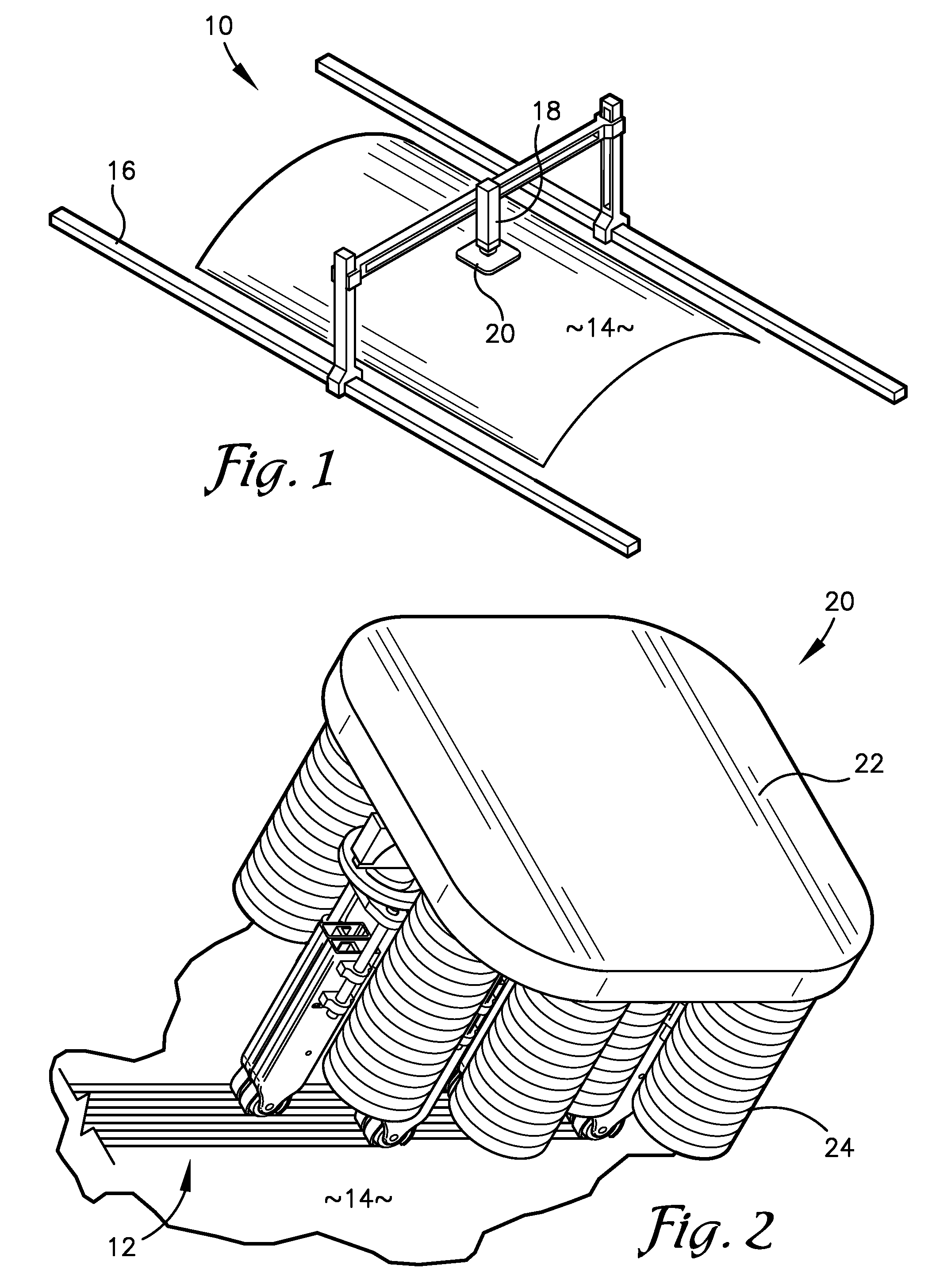
[0034]FIG. 1 illustrates a material placement system 10 constructed in accordance with an embodiment of the present invention. The material placement system 10 may be used for dispensing and compacting a material 12, illustrated in FIG. 2, onto a surface 14 of a mold, mandrel, or any apparatus for forming composite parts, and is particularly suited for fiber placement to construct composite parts for an aircraft. Referring to FIG. 1, the material placement system 10 may comprise a frame 16, a head actuator 18, and a placement head 20 attached to the frame 16 and actuated by the head actuator 18.

[0035]The frame 16 may be any structure known in the art for supporting a placement head 20, such as a gantry structure or a structure with curved or linear axes along which the placement head 20 may be moved relative to the frame 16 by the head actuator 18 or any other means known in the art. The head actuator 18 may be any actuator known in the art for moving an object along a frame. The he...


PUM

PropertyMeasurementUnit
diameteraaaaaaaaaa
diameteraaaaaaaaaa
diameteraaaaaaaaaa

Abstract

A roller assembly for bidirectionally dispensing and compacting a strip of a material onto a surface without requiring the roller assembly to rotate 180° to dispense the material in the reverse direction. The roller assembly comprises a first guide element, a second guide element, a third guide element, and a compacting roller. When the first guide element is in a first position, the strip of the material is fed to the second guide element. When the first guide element is in a second position, the strip of the material is fed to the third guide element. The compacting roller is malleable and substantially crowned around an outer circumferential surface of the compacting roller to provide even compaction to the strip of the material.

Description

BACKGROUND[0001]1. Field[0002]The present invention relates to structural and aerodynamic aircraft parts. More particularly, the present invention relates to material dispensing and compaction, such as composite tape automated fiber placement (AFP).[0003]2. Related Art[0004]Fiber placement is a method of compacting a resin-impregnated composite material, also referred to as prepreg tow, onto a surface of an item such as a tool surface, mold, mandrel, or any surface used to form composite parts. In a typical fiber placement method, multiple layers of the composite material are compacted together and cured to form a strong, light-weight component of a pre-determined shape for use in the construction of aircrafts, missiles, satellites, automobiles, etc.[0005]After dispensing and compacting material onto the surface in one direction, traditional fiber placement machines reverse directions by rotating an entire material placement head 1800. For example, in a typical application, a materi...

Claims


Application Information

Patent Timeline
Patent Type & Authority Applications(United States)
IPC IPC(8): B29C43/46
CPCB29C43/34B29C43/46B29C70/388B29C70/545Y10T156/1788B29C2043/467B29K2105/0854Y10T156/1348Y10T156/1795B29C2043/3422B29C63/04B29C70/384
Inventor WAMPLER, ROBERT RAYULLAH, MUHAMMAD ZIA
Owner SPIRIT AEROSYSTEMS
Why Eureka
Try Eureka