Permanent magnet type magnetic pole core structure capable of minimizing cogging torque for rotating electric machine

a permanent magnet and electric machine technology, applied in the direction of rotating magnets, synchronous machines with stationary armatures, electrical apparatus, etc., can solve the problems of reducing the effective output magnetic torque, affecting the control precision, and not only minimizing the cogging torque, so as to minimize the cogging torque

Inactive Publication Date: 2009-06-04
IND TECH RES INST
View PDF23 Cites 41 Cited by
  • Summary
  • Abstract
  • Description
  • Claims
  • Application Information

AI Technical Summary

Benefits of technology

[0018]It is an object of the present invention to provide to a permanent magnet type magnetic pole core structure ...

Problems solved by technology

When the driving torque is not much larger than the cogging torque, an undesired output torque ripple is generated to cause vibration and noise and further affect the control precision, especially when rotating at a very low rate.
Reducing the equivalent magnetic flux in the air gap does not only minimize the cogging torque but also reduce the effective output magnetic torque.
Therefore, such a method is seldom used to minimize the cogging torque.
However, such a method using skew rotation results in increased cost and time in manufacturing, assembly and inspection.
Using such a specific ratio, restricted...

Method used


Image

  • Permanent magnet type magnetic pole core structure capable of minimizing cogging torque for rotating electric machine
  • Permanent magnet type magnetic pole core structure capable of minimizing cogging torque for rotating electric machine
  • Permanent magnet type magnetic pole core structure capable of minimizing cogging torque for rotating electric machine

Examples


first embodiment

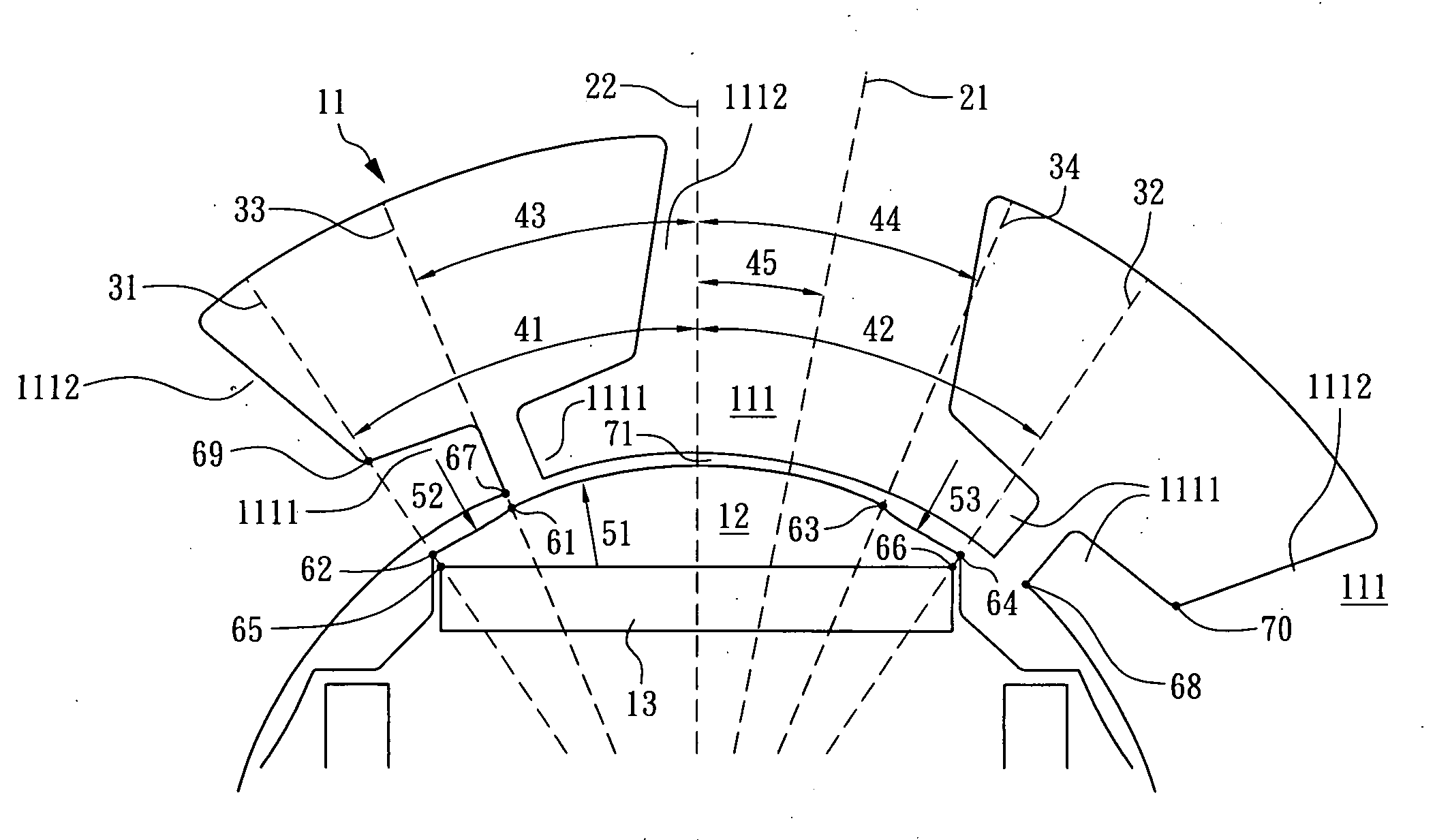
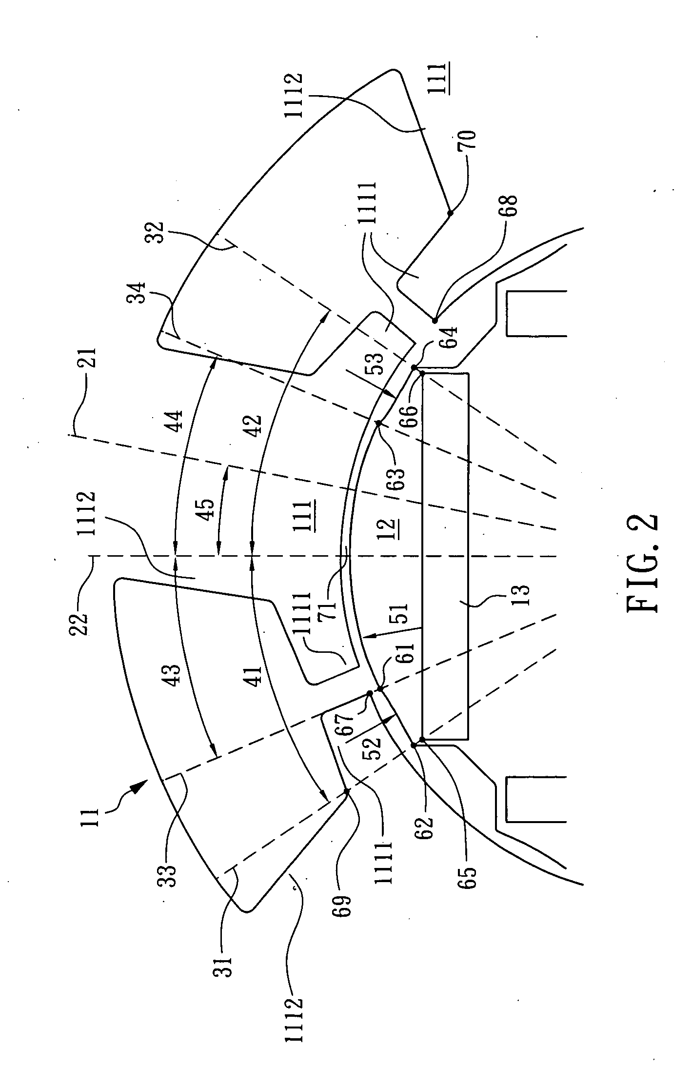
[0045]Please refer to FIG. 4 and FIG. 5 for the whole structure and the enlarged view of part of a permanent magnet type magnetic pole core structure with 4 poles and 6 slots according to the present invention. When the magnetic pole central line 22 passes through the center of the magnetic pole core 12 and the center of the permanent magnet 13 and the armature central line 21 passes through the center of the armature core 11 and the center of the tooth 111 the permanent magnet 13 faces, the center of the magnetic pole core 12 and the center of the armature core 11 are overlapped.

[0046]When the magnetic pole central line 22 and the armature central line 21 are overlapped, that is, the permanent magnet 13 faces the tooth 111 of the armature core 11, the expanding angle 43=44 and 41=42. Each magnetic pole is symmetric and repeated along the magnetic pole central line 22.

[0047]According to the present invention, the cogging torque can be eliminated during rotation using the proper perm...

second embodiment

[0050]Please refer to FIG. 7 and FIG. 8, for the whole structure and the enlarged view of part of a permanent magnet type magnetic pole core structure with 18 poles and 27 slots according to the present invention.

[0051]When the magnetic pole central line 22 passes through the center of the magnetic pole core 12 and the center of the permanent magnet 13 and the armature central line 21 passes through the center of the armature core 11 and the center of the tooth 111 the permanent magnet 13 faces, the center of the magnetic pole core 12 and the center of the armature core 11 are overlapped. The disclosure in FIG. 7 and FIG. 8 is similar to that in FIG. 4 and FIG. 5. For example, the periphery of the magnetic pole core enclosing the pole structure defining between the two reference lines is divided into a first arc surface, a second arc surface and a third arc surface. Furthermore, the magnetic pole core 12 comprises a second air gap 72 and a third air gap 73 on both sides of the perma...


PUM


Abstract

A permanent magnet type magnetic pole core structure capable of minimizing the cogging torque for a rotating electric machine such as an electric motor or a power generator is disclosed. The rotating electric machine comprises: a magnetic pole core and an armature core. The magnetic pole core comprises a plurality of magnetic pole structures in a number of M, while each magnetic pole structure comprises at least one permanent magnet and can be used for defining two reference lines with an expanding angle sandwiched therebetween, and a periphery of the magnetic pole core enclosing the pole structure defining between the two reference lines is divided into a first arc surface, a second arc surface and a third arc surface. In an exemplary embodiment, the armature core comprises a plurality of slot structures in a number of S. The ratio of the amount of slot structure to the amount of the magnetic pole structure, i.e. S/M, is 3/2. With the aforesaid permanent magnet type magnetic pole core structure, the cogging torque of the rotating electric machine can be minimized.

Description

BACKGROUND OF THE INVENTION[0001]1. Field of the Invention[0002]The present invention generally relates to a permanent magnet type magnetic pole core structure capable of minimizing the cogging torque for a rotating electric machine and, more particularly, to a permanent magnet type magnetic pole core structure capable of minimizing the cogging torque for a rotating electric machine such as an electric motor or a power generator.[0003]2. Description of the Prior Art[0004]In order to enhance the efficiency, increase the power density and minimize the relative size of a rotating electric machine (such as an electric motor and a power generator), a permanent magnet is used as a constant magnetic source. With the development in processing and materials, the permanent magnet with high magnetic energy product is widely used in rotating electric machines.[0005]Please refer to FIG. 1, wherein the rotating electric machine comprises: a stator 91, rotor 92 and a magnet 93. The periphery of th...

Claims


Application Information

Patent Timeline
IPC IPC(8): H02K21/12
CPCH02K29/03H02K1/276
Inventor HUNG, SHIH-WEI
Owner IND TECH RES INST
Why Eureka
Try Eureka