Apparatus for supporting an audio/video system which includes a thin screen video display unit

Inactive Publication Date: 2009-06-04
FREEMAN BASIL NORMAN
View PDF12 Cites 8 Cited by
  • Summary
  • Abstract
  • Description
  • Claims
  • Application Information

AI Technical Summary

Benefits of technology

[0006]The exterior housing comprises a front panel, a rear panel, and opposed side panels extending between the front and rear panels and upwardly from a base of the housing to a top of the housing, the latter including a narrow, elongated opening sized to permit upward and downward movement of the display unit through the opening. The video and audio components are fixedly mounted to the housing. In preferred embodiments, the rear panel, side panels and top are formed as a single unit which is removably connectable with the base. This facilitates ease of access to the interior of the housing when servicing or repair is necessary.
[0008]Apparatus in accordance with the present invention can be readily configured in a slim, compact manner allowing for optimal television viewing whilst maintaining an attractive appearance and remaining portable or easily movable from one location to another. Movement around the home or an office can be done safe in the knowledge that sensitive electronic components are housed in a protected position inside the apparatus.
[0009]Further, the apparatus can be easily set-up to require no external peripheral devices such as a DVD player or amplifiers or speakers. This feature can prove to be advantageous for those who do not wish to be bothered with the laborious task of purchasing and setting-up external peripheral devices. Typically, a user would only have to connect to a mains electrical outlet to view DVD's and to desired external media sources (e.g. a cable connection).
[0010]In addition to the foregoing, the present invention possesses various benefits and advantages over known retractable thin screen and Cathode Ray Tube (CRT) televisions. In particular the invention can be mass produced at a lower cost since it only requires that the thin screen video display unit can be extended and retracted. Other known thin screen retractable television enclosures require that all of the main components be retracted. This requirement necessitates the use of relatively heavy-duty lifting mechanisms such as chain drive or rack and pinion type mechanisms. Because less weight is carried, the present invention can use a simple drive belt mechanism which is faster, quieter and more economical to manufacture.
[0012]A further practical example of the flexibility possessed by the present invention is utilization in locations with limited space. As indicated above, the apparatus can be unobtrusive and can compliment the decor of small rooms when the thin screen video display unit is in a retracted position. It can be advantageously set-up in the smaller sized rooms typically found in hotels and hospitals. As it is portable or easily movable, it readily can be removed for repair and / or replacement as required.
[0013]A further practical example of the flexibility possessed by the present invention is it's use in educational institutions where portability and ease of set-up are important features. Whilst the screen is in its retracted position, it and sensitive audio / video components will be well protected from physical harm when stored in an unsupervised environment.

Problems solved by technology

When so mounted, they often are no longer portable or otherwise easily movable from one room in a house or apartment to allow viewing in another room of the house or an apartment.
Further, in a variety of home environments, such televisions can have an unwanted dominant presence within a given room at times when it is desired to use the room for other purposes.

Method used


Image

  • Apparatus for supporting an audio/video system which includes a thin screen video display unit
  • Apparatus for supporting an audio/video system which includes a thin screen video display unit
  • Apparatus for supporting an audio/video system which includes a thin screen video display unit

Examples


Embodiment Construction

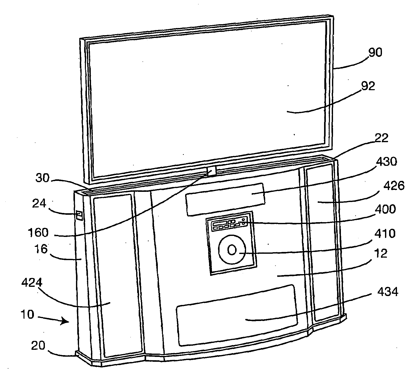
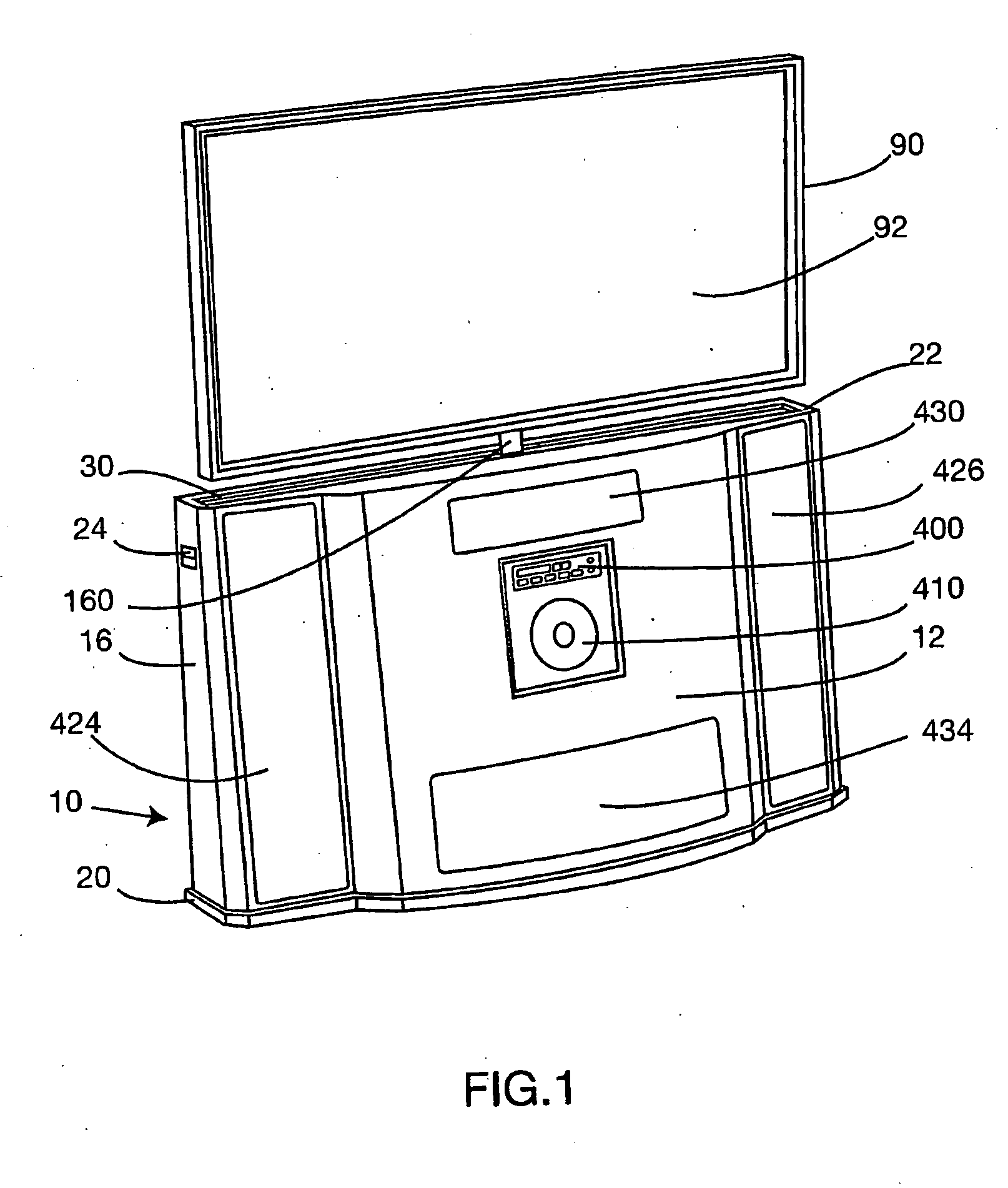
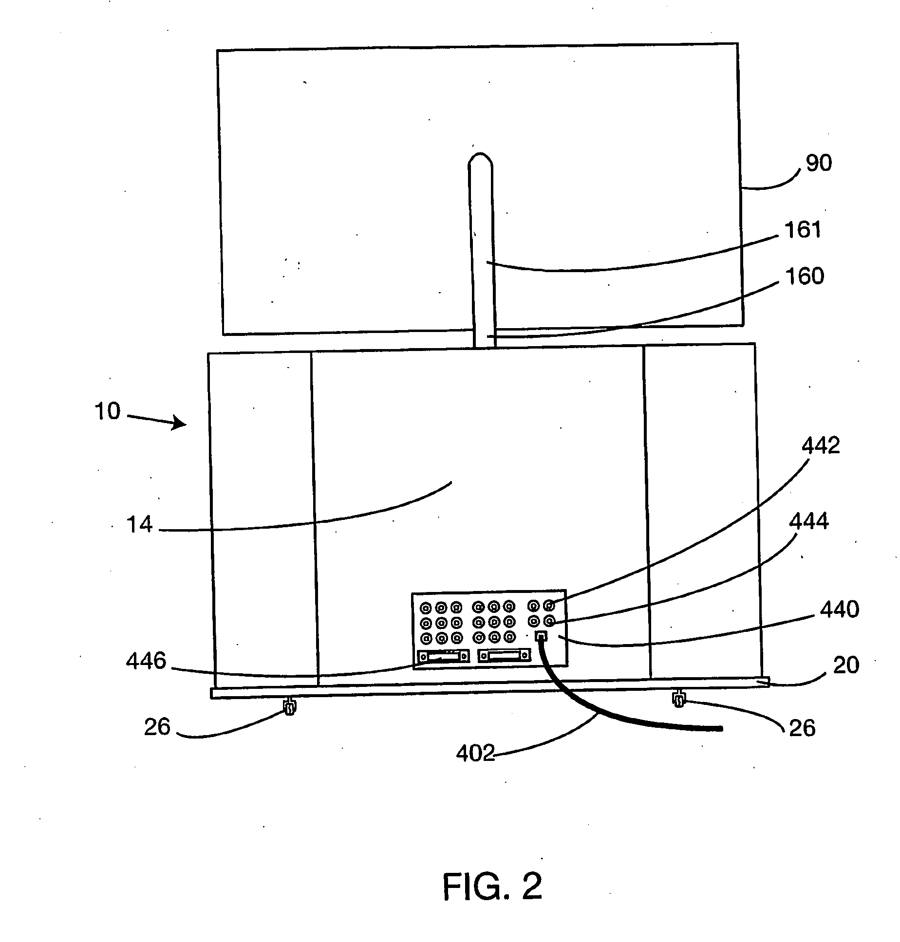
[0025]Apparatus for supporting an audio / video system constructed in accordance with the present invention is shown in an assembled condition in FIGS. 1-6. The apparatus includes an exterior housing generally designated 10, such housing including a front panel 12, a rear panel 14, and opposed side panels 16, 18 extending between the front and rear panels. All of such panels extend upwardly from a base 20 of the housing to a top 22 of the housing.

[0026]As indicated in FIG. 7, front panel 12 is connected to base 20 by means of L-shaped brackets 50 which are secured to both panel 12 and base 20 (e.g. with screws). Rear panel 14, side panels 16, 18 and top 22 are formed as a single unit which is releasably connectable to front panel 12 (e.g. with screws). The panels, base 20 and top 22 should all be formed from sturdy material, preferably laminated wood or a suitable polymeric material.

[0027]Side panels 16, 18 each include a handle recess 24 to facilitate movement and lifting of the appa...


PUM


Abstract

Apparatus for supporting an audio / video system, the system including a thin screen video display unit, video components operatively coupled to the display unit for generating video signals displayable by the unit, and audio components for generating audio signals, includes an elevator mechanism for the display unit and an exterior housing. The exterior housing includes a top opening sized to permit upward and downward movement of the display unit through the opening. The video and audio components are fixedly mounted to, the housing. The elevator mechanism extends upwardly within the housing and comprises an elevator platform adapted to carry the display unit between a lower position where the display unit when carried by the platform is retracted into the mechanism and an upper position where the display unit when carried by the platform is deployed above both the elevator mechanism and the exterior housing. In preferred embodiments, the apparatus includes a swivel mounting for supporting the display unit and permitting rotational movement thereof with respect to the platform when the platform is in its upper position.

Description

CROSS-REFERENCE TO RELATED APPLICATIONS[0001]This application is related to U.S. provisional application No. 60 / 1538,216 filed Jan. 23, 2004, entitled “APPARATUS FOR SUPPORTING AN AUDIO / VIDEO SYSTEM WHICH INCLUDES A THIN SCREEN VIDEO DISPLAY UNIT”, naming Basil Norman Freeman as the inventor. The contents of the provisional application are incorporated herein by reference in their entirety, and the benefit of the filing date of the provisional application is hereby claimed for all purposes that are legally served by such claim for the benefit of the filing date.BACKGROUND OF THE INVENTION[0002]The present invention relates generally to apparatus for supporting an audio / video system which includes a thin screen video display unit and related audio / video components such as tuners and other user controls, loudspeakers, and electrical and electronic circuitry and subsystems.[0003]With the introduction of new technologies, there has been a proliferation of new television sets with thin s...

Claims


Application Information

Patent Timeline
IPC IPC(8): A47B81/06A47B51/00H04N5/64H04N5/655H05K5/00H05K7/00
CPCH05K5/0017H04N5/642
Inventor FREEMAN, BASIL NORMAN
Owner FREEMAN BASIL NORMAN
Why Eureka
Try Eureka