Configurable image trigger for a vision system and method for using the same

Active Publication Date: 2013-06-20
COGNEX CORPORATION
View PDF1 Cites 7 Cited by
  • Summary
  • Abstract
  • Description
  • Claims
  • Application Information

AI Technical Summary

Benefits of technology

[0009]This invention overcomes disadvantages of the prior art by providing a user-configurable trigger for a vision system that can be set using a user interface that allows the straightforward variation of a plurality of exposed trigger parameters. Illustratively, the configuration of triggers is performed in a manner similar to the programming of inspection tasks, using the interface. Illustratively, the vision system includes a triggering mode in which the system keeps acquiring (i.e. continuously acquires) images of a field of view with respect to objects in relative motion. The system runs user-configurable “trigger logic”. When the trigger logic succeeds/passes, the current image or a newly acquired image is then transmitted to the main inspection logic for processing. As a user-configurable trigger logic, it can be readily configured by a user operating an interface, which can also be used to configure the main inspection process, to trigger the vision system by tools such as presence-absence, edge finding, barcode finding, pattern matching, image thresholding, or any arbitrary combination of tools exposed by the vision system in the interface. Notably, the illustrative embodiments provide the user the ability to arbitrarily configure the trigger logic using the tools exposed by the vision system in an effort to afford the user substantial flexibility to customize trigger criteria to a specific vision system task.
[0010]In an illustrative embodiment, a system and method for using a configurable trigger for a vision system includes a vision system camera that acquires images objects moving relative to a field of view of the camera. A vision system interface is constructed and arranged to allow user access to a plurality of vision system tools to process t

Problems solved by technology

This approach entails additional hardware and has limited ability to modify the conditions for triggering.
However, even when a system has such a native image triggering mode, that mode is typically very rigid such that if a user desires to apply even a slight change to the trigger mode, the system's software would most likely require a change and/or upgrade.
The user would not, for example, be able to arbitrarily add a filter to the image trigger.
Other potential disadvantages of internal (within the vision system) and ex

Method used


Image

  • Configurable image trigger for a vision system and method for using the same
  • Configurable image trigger for a vision system and method for using the same
  • Configurable image trigger for a vision system and method for using the same

Examples


Example

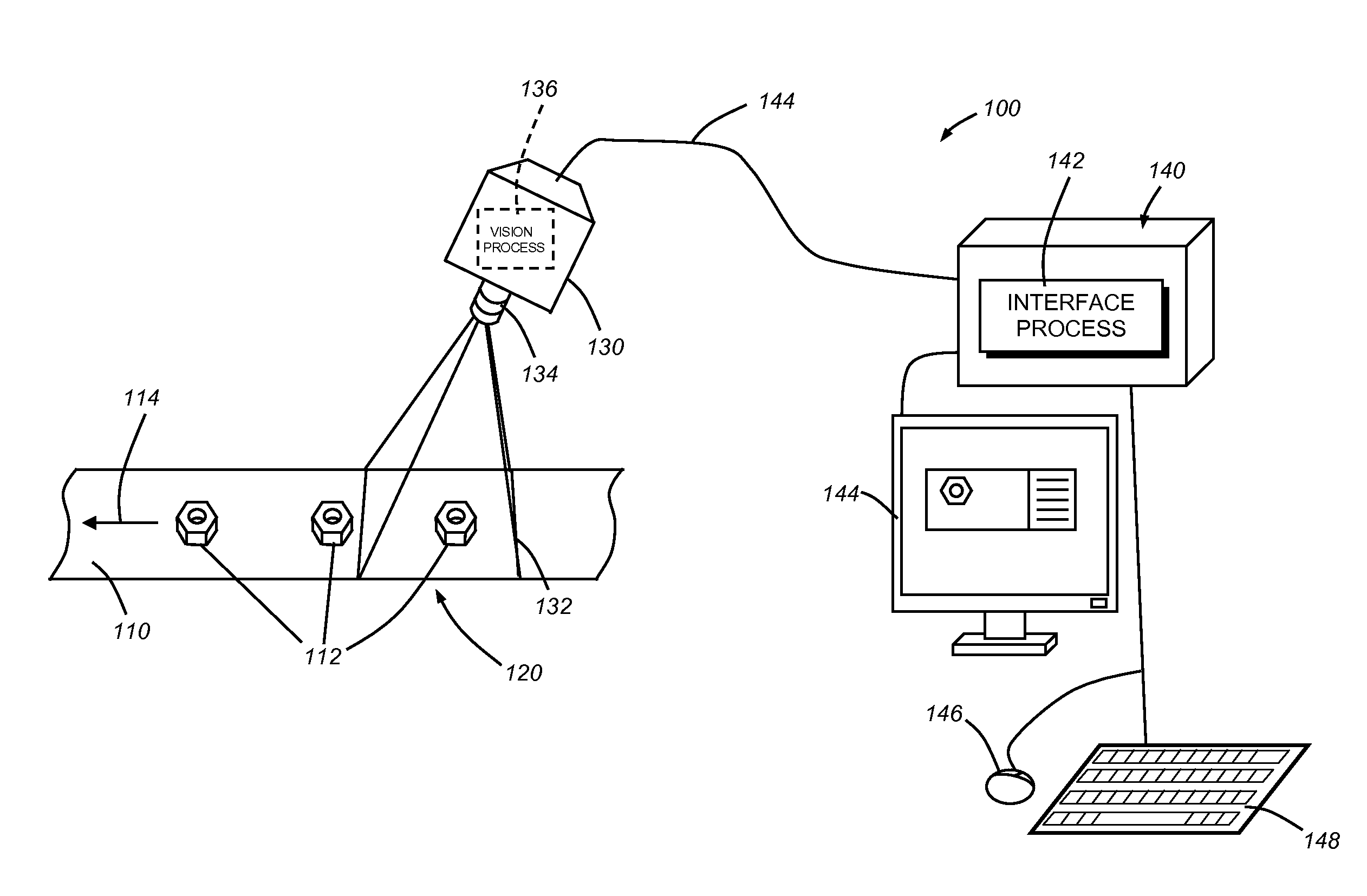
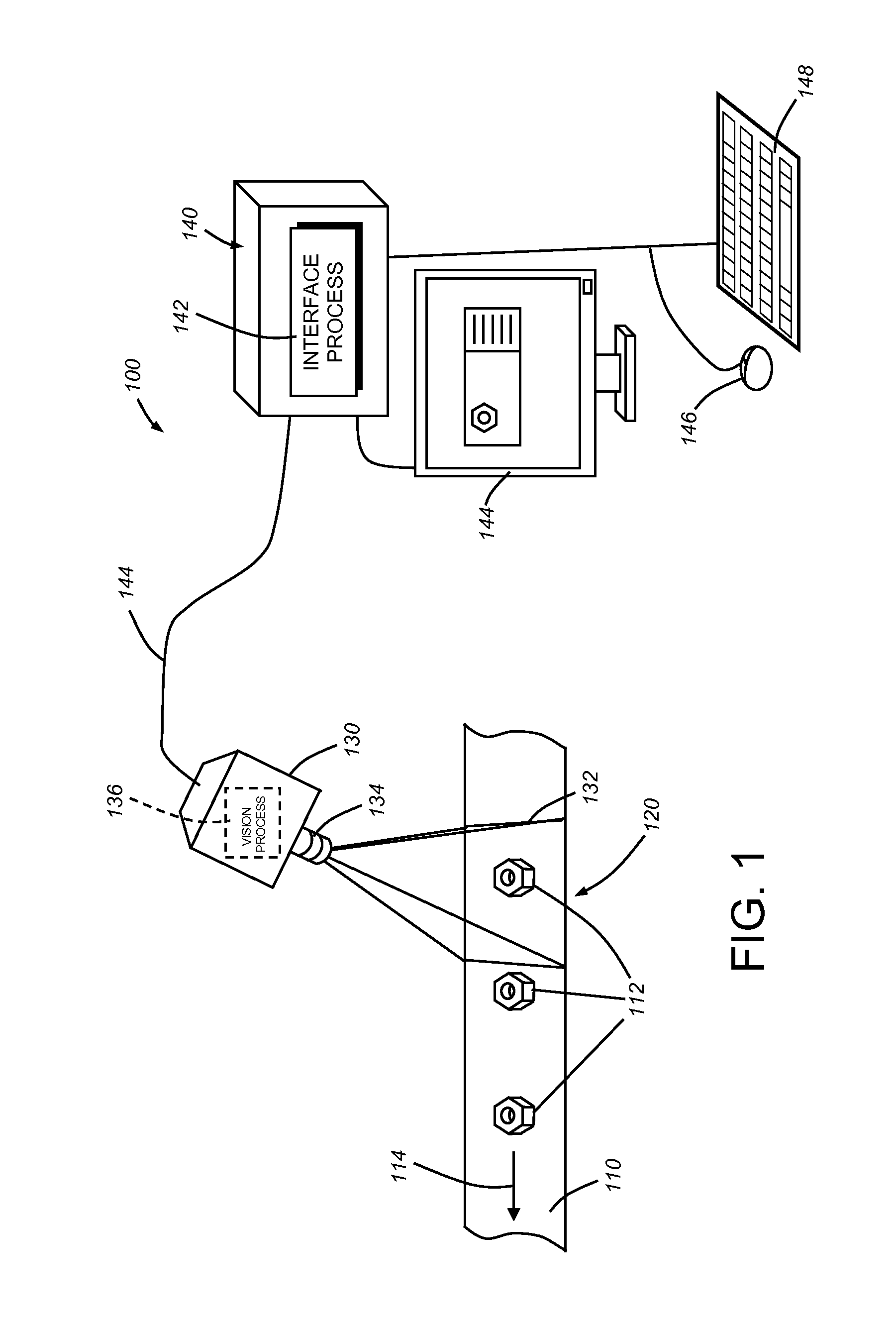
[0024]FIG. 1 shows a manufacturing arrangement 100 that includes an exemplary, moving production line 110 that directs a plurality of objects 112 in a direction (arrow 114) though the inspection location 120 at which a vision system camera 130 is positioned. An illuminator (not shown) can be provided to the camera and / or at a location remote from the camera so as to illuminate the field of view 132 at the inspection location. The camera 130 in this embodiment includes an appropriate lens 134, adapted to image the field of view 132 and the object 112 therein with appropriate levels of detail. An appropriate image sensor (not shown) mounted orthogonally to the optical axis within the camera is used to capture the image and convert it to pixel data, typically in grayscale, but optionally in color. The vision system camera 130 can include an on-board vision process / processor (dashed block 136), which performs the system's image acquisition and image processing tasks.

[0025]An example of ...


PUM


Abstract

This invention provides a trigger for a vision system that can be set using a user interface that allows the straightforward variation of a plurality of exposed trigger parameters. Illustratively, the vision system includes a triggering mode in which the system keeps acquiring an image of a field of view with respect to objects in relative motion. The system runs user-configurable “trigger logic”. When the trigger logic succeeds/passes, the current image or a newly acquired image is then transmitted to the main inspection logic for processing. The trigger logic can be readily configured by a user operating an interface, which can also be used to configure the main inspection process, to trigger the vision system by tools such as presence-absence, edge finding, barcode finding, pattern matching, image thresholding, or any arbitrary combination of tools exposed by the vision system in the interface.

Description

FIELD OF THE INVENTION[0001]This invention relates to vision systems and more particularly to automated trigger functions in a vision system.BACKGROUND OF THE INVENTION[0002]Machine vision systems are used in a wide range of manufacturing processes. Among other uses, machine vision is employed to ensure quality and to assist in the constructing various articles and devices. A common use for vision systems in industrial applications is in association with an inspection or assembly location on a moving production line. Images of objects are acquired as they pass under the vision system camera's field of view. Based upon image data acquired, the vision system can decide whether there is a flaw in the object, determine its alignment for further processes, operate a robot manipulator, identify and sort the object into an appropriate bin, or perform other automated tasks.[0003]In a typical implementation, the triggering of image acquisition by the vision system is performed according to a...

Claims


Application Information

Patent Timeline
IPC IPC(8): H04N7/18
CPCG01N21/8806G01N21/8851G06F3/04847G01N2021/8887G01N2021/8867
Inventor MAHUNA, TYSON
Owner COGNEX CORPORATION
Why Eureka
Try Eureka