Antenna Device and Radio-Communication System Using the Same

Inactive Publication Date: 2009-06-04
PANASONIC CORP
View PDF8 Cites 68 Cited by
  • Summary
  • Abstract
  • Description
  • Claims
  • Application Information

AI Technical Summary

Benefits of technology

[0005]The present invention provides an antenna device comprising: a substrate; a ground conductor provided on the bottom surface of the substrate; a radiation conductor, with a partial cut-out, provided on the top surface of the substrate; a ground terminal provided on the partial cut-out in the radiation conductor; a conductor connected between the ground conductor and ground terminal; and a feed terminal connected to the radiation conductor, wherein the ground terminal and the feed terminal are con

Problems solved by technology

However, when the tag is attached on a metal plate to communicate data a problem occurs that the antenna in the tag doesn't function well owing to an influence from the metal plate.
The both

Method used


Image

  • Antenna Device and Radio-Communication System Using the Same
  • Antenna Device and Radio-Communication System Using the Same
  • Antenna Device and Radio-Communication System Using the Same

Examples


embodiment

Preferred Embodiment

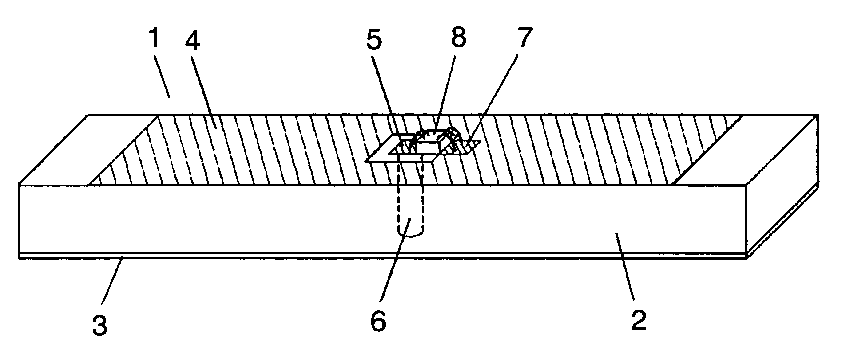
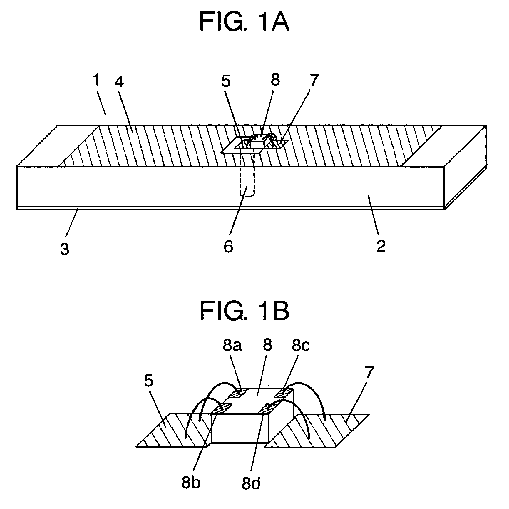
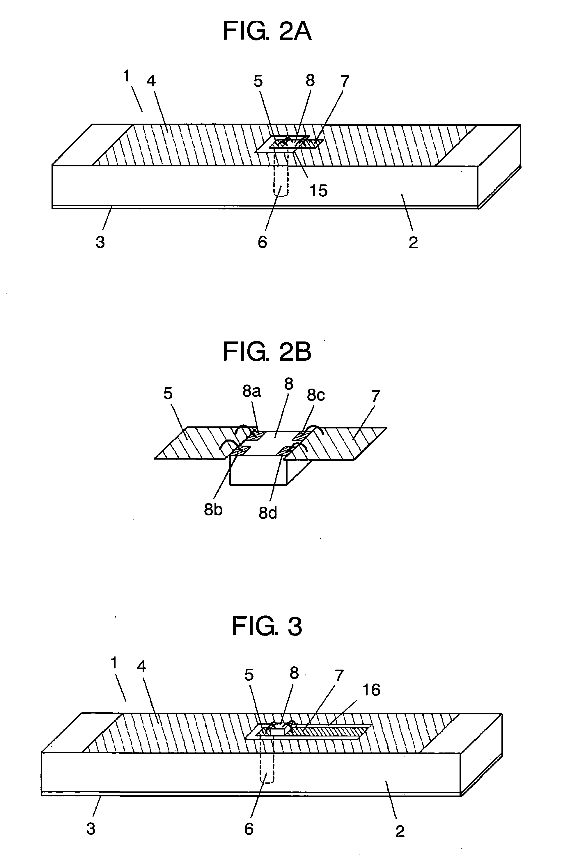
[0031]FIG. 1A shows a perspective view of antenna device 1 of the present invention. Antenna device 1 comprises; substrate 2; ground conductor 3 provided on the bottom surface of substrate 2; radiation conductor 4, with a partial cut-out, provided on the top surface of substrate 2; ground terminal 5 provided in the partial cut-out of radiation conductor 4; conductor 6 connected between ground terminal 5 and ground conductor 3; and feed terminal 7 connected to radiation conductor 4. Conductor 6 connects ground conductor 3 with ground terminal 5 electrically and is formed for instance by through-hole or the like. IC chip 8 is mounted between ground terminal 5 and feed terminal 7. Ground electrodes 8a and 8b of IC chip 8 are connected to ground terminal 5, and ground electrodes 8c and 8d to feed terminal 7 respectively by for instance wire bonding or the like as shown in FIG. 1B. In this way, electric energy is fed to radiation conductor 4. To protect IC chip 8 and ...


PUM


Abstract

An antenna device comprising: a substrate; a ground conductor provided on the bottom surface of the substrate; a radiation conductor, with a partial cutout, provided on the top surface of the substrate; a ground terminal provided on the partial cutout of the radiation conductor; a conductor connecting the ground conductor with the ground terminal; and a feed terminal connected to the radiation conductor, wherein the ground terminal and the feed terminal are connected via an IC chip is provided. The configuration can realize an antenna device capable of feeding electric power through the IC chip, and of operating even on a metal plate fully well. A radio communication system using the antenna device is provided additionally.

Description

TECHNICAL FIELD[0001]The present invention relates to an antenna device for use in radio-communication system.BACKGROUND ART[0002]The RFID (Radio Frequency Identification) system, an example of radio-communication system, is a generic term referring to an identification technology utilizing radio waves. In recent years, the contactless communication system by radio waves in combination with identification technology utilizing IC chip has become a mainstream in the field. Specifically, a device called a reader / writer retrieves data stored in an IC chip embedded in tag or label shaped antenna attached on persons or objects to identify the persons or the objects.[0003]Japanese Patent Unexamined Publication No. 2004-104344 discloses an example of an antenna for the RFID tag. A conventional dipole antenna is described with reference to FIG. 9. The dipole antenna shown in FIG. 9 comprises dielectric sheet 100, radiation element 101 and IC chip 102, wherein IC chip 102 feeds electric power...

Claims


Application Information

Patent Timeline
IPC IPC(8): H01Q1/36H01Q1/48
CPCG06K19/07749G06K19/07771H01Q9/0471H01L2224/48091H01L2224/48227H01L2924/19041H01L2924/30107H01L2924/3011H01Q1/22H01Q1/2208H01Q1/243H01Q1/38H01Q9/0407H01Q9/0442H01L2924/00014
Inventor SASAGAWA, MISAKOIGUCHI, AKIHIKOSATOH, YUKI
Owner PANASONIC CORP
Why Eureka
Try Eureka