Voice response system

a voice response and voice technology, applied in the field of automatic voice response systems, can solve the problems of frustrating and inconvenient routed to an operator, voice response systems may not be able to provide an appropriate automatic response, and speech recognition software failures, etc., to achieve the effect of quick understanding the stag

Active Publication Date: 2009-06-04
NUANCE COMM INC
View PDF42 Cites 19 Cited by
  • Summary
  • Abstract
  • Description
  • Claims
  • Application Information

AI Technical Summary

Benefits of technology

[0030]The present invention solves the problems described above. The present invention makes it possible, by using a dialog history log of a voice response system at the time of forwarding to an operator, to determine and visually present, to the operator in an easily understandable manner, the content of an inquiry from a user and the current dialog state in a session between the user and the voice response system. This allows the operator to quickly learn the current dialog state and smoothly provide a response to the user.
[0041]The present invention allows the operator to quickly understand the stage or state of the dialog at the time of forwarding to the operator. Moreover, the operator can quickly understand the reliability of each item already entered at the time of forwarding. This enables the operator, for example, to do away with the confirmation of an item with high reliability, or prompts the operator to ask the user again about an item with low reliability for confirmation. Moreover, the operator can quickly understand, for the items already entered, an input history of past entries.

Problems solved by technology

In a telephone environment, situations can exist in which a voice response system may be unable to provide an appropriate automatic response during a user call.
Examples of such situations include failure of speech recognition software or a user asking a question to which the system is not programmed to respond.
Being routed to an operator can be frustrating and inconvenient for the user, particularly where the operator asks the user to start over from the beginning of the inquiry.
Having to make a suitable number of human operators available to avoid high levels of customer dissatisfaction also increases the service provider's costs.
It may take a significant amount of time to complete these actions, making the approach inconvenient for the user and inefficient from the service provider's point of view.
In such a system, the flow or transition of a session is limited by restricting the vocabulary the system will recognize at each stage of processing.
Therefore, it is difficult to quickly determine the current dialog state simply by considered previously entered responses.
Even where a caller is forwarded to a human operator for help, simply displaying previously entered responses is inadequate for understanding the current dialog state, for the reasons described below.
No known prior art discloses a system with capabilities sufficient to perform such a function, or a method for solving the problems described above.

Method used


Image

  • Voice response system
  • Voice response system
  • Voice response system

Examples


operation example 1

[0129]If

[0130]Pr(State 1 |ResID(t), ResID(t−1))=0.5,

[0131]Pr(State 2 |ResID(t), ResID(t−1))=0.3, and

[0132]Pr(State 3 |ResID(t), ResID(t−1))=0.2,

max(0.5, 0.3, 0.2)=0.5 is obtained. This gives S(t)=State 1.

operation example 2

[0133]If there is no Si that satisfies Pr(Si|ResID(t), ResID(t−1))>0, and

[0134]Pr(State 1|ResID(t))=0.2,

[0135]Pr(State 2|ResID(t))=0.7, and

[0136]Pr(State 3|ResID(t))=0.2,

max(0.2, 0.7, 0.2)=0.7 is obtained. This gives S(t)=State 2.

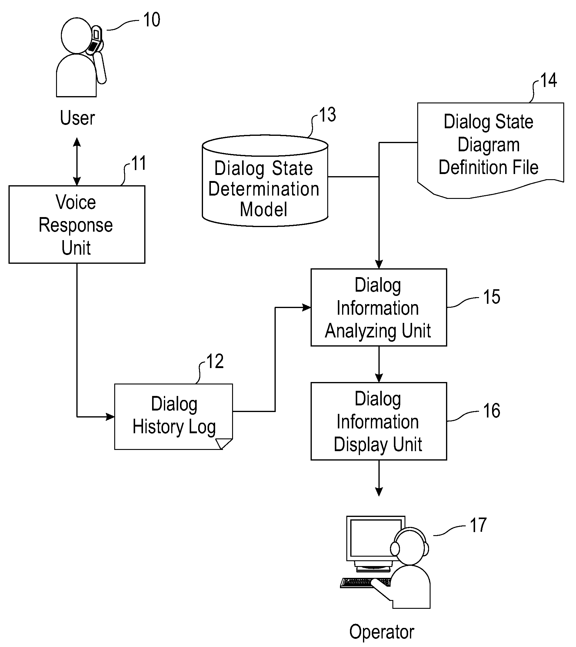
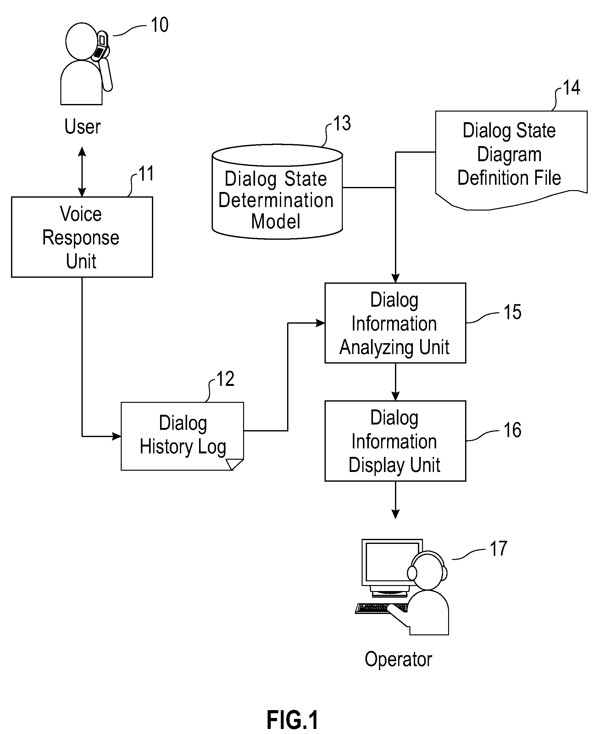
[0137]Generally, the dialog state determination model 13 can be expressed as S(t)=F(log for time “t0” through time “t”, dialog state for time “t0” through time “t”), where “t0” is a service start time, “t” is a current time, S(t) is a current dialog state, and F is a function for determining the current dialog state. In the example described above, input parameters for F are ResIDs (response sentence IDs) and past state S. It is possible to add results of recognition of user's speech to these input parameters. The dialog state determination model 13 may be a statistical model in which learning is done from an existing log as in the case of the example above, or may be a rule-based model as described below.

[0138]The following is a description of a procedure ...

example 3

DIALOG EXAMPLE 3

[0153]System: Welcome to the train information system. How may I help you?

[0154]User: What is the last train from Tokyo to Kobe?

[0155]System: The last train from Tokyo to Kome?

[0156]User: To Kobe, please.

[0157]System: The last train from Tokyo to Kome?

[0158]User: To Kobe.

[0159]System: The last train from Tokyo to Konu?

[0160]FIG. 7 illustrates a screen displaying a dialog state of Dialog State 1 in the above Example. The dialog state is “last train search confirmation in progress”46. Of items already entered, “departure station”51 has a high reliability, “arrival station”52 has a low reliability, and “date of use”53, “train name”55, and “train type”56 are entered as default values. Also, it is indicated that the user has gone through the states of “service start”41, “service selection in progress”42, and “last train search input in progress”45 to reach the current dialog state “last train search confirmation in progress”46. In this example, “Kobe” that the user wishes...


PUM


Abstract

A voice response system attempts to respond to spoken user input and to provide computer-generated responses. If the system decides it cannot provide valid responses, the current state of user session is determined and forwarded to a human operator for further action. The system maintains a recorded history of the session in the form of a dialog history log. The dialog history and information as to the reliability of past speech recognition efforts is employed in making the current state determination. The system includes formatting rules for controlling the display of information presented to the human operator.

Description

TECHNICAL FIELD[0001]The present invention relates to automated voice response systems and particularly to a system, method, and program for determining a dialog state during a user session involving such a voice response system.BACKGROUND OF THE INVENTION[0002]In a telephone environment, situations can exist in which a voice response system may be unable to provide an appropriate automatic response during a user call. Examples of such situations include failure of speech recognition software or a user asking a question to which the system is not programmed to respond. In such situations, the user call is typically forwarded to a human operator, who must personally deal with the user's inquiry. Being routed to an operator can be frustrating and inconvenient for the user, particularly where the operator asks the user to start over from the beginning of the inquiry. Having to make a suitable number of human operators available to avoid high levels of customer dissatisfaction also incr...

Claims


Application Information

Patent Timeline
Patent Type & Authority Applications(United States)
IPC IPC(8): H04M1/64G10L15/00
CPCH04M3/493G10L15/22
Inventor HORIOKA, MASARUATAKE, YOSHINORITAHARA, YOSHINORI
Owner NUANCE COMM INC
Why Eureka
Try Eureka