Network bandwidth detection and distribution

a network bandwidth and detection technology, applied in the field of network bandwidth detection and distribution, can solve the problems of large latency, difficult initial bandwidth estimation, and long recovery tim

Active Publication Date: 2009-06-04
SONY COMPUTER ENTERTAINMENT INC
View PDF102 Cites 33 Cited by
  • Summary
  • Abstract
  • Description
  • Claims
  • Application Information

AI Technical Summary

Problems solved by technology

It is noted that initial bandwidth estimation is rather difficult problem.
Such flooding may cause a large latency that may take long time to recover.
The inventors have observed that without padding, the receiver starts allocating more bandwidth than the network can actually handle, and then when the video and audio data use up the full available bandwidth, growth of delay or packet loss (degradation of quality) occurs.
In some situations the accuracy of time determined by NTP may not be good enough to detect propagation delays of order 10 milliseconds.
Rate limitation, which may occur either intentionally or unintentionally, could happen at any layer in the protocol stack.
A long queue increases latency, which is undesirable.
Long queues also tend to take a long time to be recovered.
However, as the data transmission rate approaches the bandwidth limit BWL for the network path, the transmission rate will tend to flatten off as a function of packet size.
This causes an increase in the number of packets, and a consequent decrease in the transfer rate since the bandwidth is pps limited.
“Session” information, such as whether a session involves a direct connection or via a proxy server or a relay server, is not useful because bottle necks may be present at locations other than a proxy or a relay server, (e.g., an ADSL uplink.)
Existing bandwidth measurement schemes, however, only determine inbound bandwidth saturation.
It is noted that packet loss or delay may be caused by other reasons.

Method used


Image

  • Network bandwidth detection and distribution
  • Network bandwidth detection and distribution
  • Network bandwidth detection and distribution

Examples


Embodiment Construction

[0024]Although the following detailed description contains many specific details for the purposes of illustration, anyone of ordinary skill in the art will appreciate that many variations and alterations to the following details are within the scope of the invention. Accordingly, the exemplary embodiments of the invention described below are set forth without any loss of generality to, and without imposing limitations upon, the claimed invention.

TECHNICAL BACKGROUND

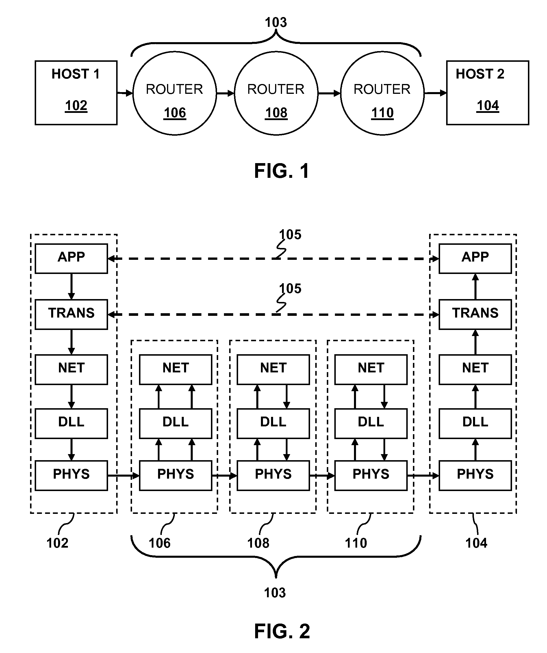
[0025]Embodiments of the present invention may be understood in the context of network communications. FIG. 1 illustrates an example of network communication between Host 1102 and Host 2104. By way of example, the hosts may be any network capable device. Such devices include, but are not limited to computers, hand held internet browsers and / or email devices, Voice over Internet Protocol (VoIP) phones, video game consoles, hand held video game devices, and the like. Messages from Host 1 travel to Host 2 over a network path...


PUM


Abstract

In a node configured to communicate with one or more other nodes over a network, available bandwidth for network traffic may be distributed among two or more distinct channels of communication within a single application running on the node. An available bandwidth may be detected for communication between the first node and a second node. A distribution may be determined for the available bandwidth among the two or more communication channels. A sending rate may be adjusted for data sent from the first node to the second node over one or more of the two or more communication channels in response to a detected change in the available bandwidth.

Description

CLAIM OF PRIORITY[0001]This application claims the priority benefit of commonly-assigned, co-pending U.S. Provisional Patent application No. 60 / 992,295 to James E. Marr, Yutaka Takeda, Attila Vass, Payton White and Stephen C. Detwiler entitled “NETWORK TRAFFIC PRIORITIZATION” (Attorney Docket Number SCEA06084US00), filed Dec. 4, 2007, the entire disclosures of which are incorporated herein by reference.[0002]This application claims the priority benefit of commonly-assigned, co-pending U.S. Provisional Patent application No. 60 / 992,282 to Yutaka Takeda, James E. Marr, Stephen C. Detwiler, Attila Vass, and Payton White entitled “NETWORK BANDWIDTH DETECTION AND DISTRIBUTION”, filed Dec. 4, 2007, the entire disclosures of which are incorporated herein by reference.CROSS-REFERENCE TO RELATED APPLICATION[0003]This application is related to commonly-assigned, co-pending U.S. patent application No. 12 / ______ to James E. Marr, Yutaka Takeda, Attila Vass, Payton White and Stephen C. Detwiler ...

Claims


Application Information

Patent Timeline
Patent Type & Authority Applications(United States)
IPC IPC(8): G06F15/173H04L47/52H04L47/525
CPCH04L12/5693H04L47/521H04L29/06H04L29/08072H04L47/525H04L47/50H04L69/329H04L9/40
Inventor TAKEDA, YUTAKAMARR, JAMES E.DETWILER, STEPHEN C.VASS, ATTILAWHITE, PAYTON R.
Owner SONY COMPUTER ENTERTAINMENT INC
Why Eureka
Try Eureka