Architectural Structure, Structural Unit and Method for Constructing the Same

a technology for building structures and structures, applied in the direction of buildings, buildings, constructions, etc., can solve the problems of not being able to use this structure, and not being able to provide a tube frame, so as to improve the workability of construction, reduce the work load, and increase the size and weight

Inactive Publication Date: 2009-06-11
SEKISUI CHEM CO LTD
View PDF0 Cites 9 Cited by
  • Summary
  • Abstract
  • Description
  • Claims
  • Application Information

AI Technical Summary

Benefits of technology

[0050]The structural units that are connected with each other as described above can be disposed so as to cover the apexes and sides of all hexagonal cells that constitute the virtual honeycomb configuration. That is, when reference is made to one hexagonal cell, a plurality (six, five, four or three) structural units are connected in a ring shape along the six sides of the hexagonal cell with an opening formed in the mid portion, thus realizing an architectural structure having a main frame of honeycomb configuration that is erected vertically and expands in a plane. Particularly the circumferential surface of the tube frame can be formed in a honeycomb structure. In addition, a slab can be installed at any desired position of the structural unit that constitutes the main frame of honeycomb configuration, so that the height of each story can be freely set.
[0071]In addition, the construction method of the present invention is a dry method that eliminates the need of curing of concrete required in a wet process such as reinforced concrete structure with on-site concrete placement, thus resulting in a shorter period of construction work.

Problems solved by technology

This construction method has such a drawback that the presence of a beam in every span poses a significant restriction on the design of interior space.
However, the center at which all the legs join is where the stress is concentrated, and therefore it is not desirable in terms of structural stability to connect all the column members to one joint member at the center.
As a result, it is not possible to use this structure to form the flat or curved surface of a tube frame formed from hexagonal cells connected together in a honeycomb configuration.
Thus the inventions of Japanese Unexamined Patent Publication (Kokai) No. 61-83738 and Japanese Unexamined Patent Publication (Kokai) No. 53-43217 are not capable of providing a tube frame having a main frame of honeycomb configuration formed by connecting structural units together.

Method used


Image

  • Architectural Structure, Structural Unit and Method for Constructing the Same
  • Architectural Structure, Structural Unit and Method for Constructing the Same
  • Architectural Structure, Structural Unit and Method for Constructing the Same

Examples


example 1

[0147]By making reference to FIGS. 7 to 14, examples of architectural structures having a main frame formed by connecting structural units that are disposed in a virtual honeycomb configuration will be described.

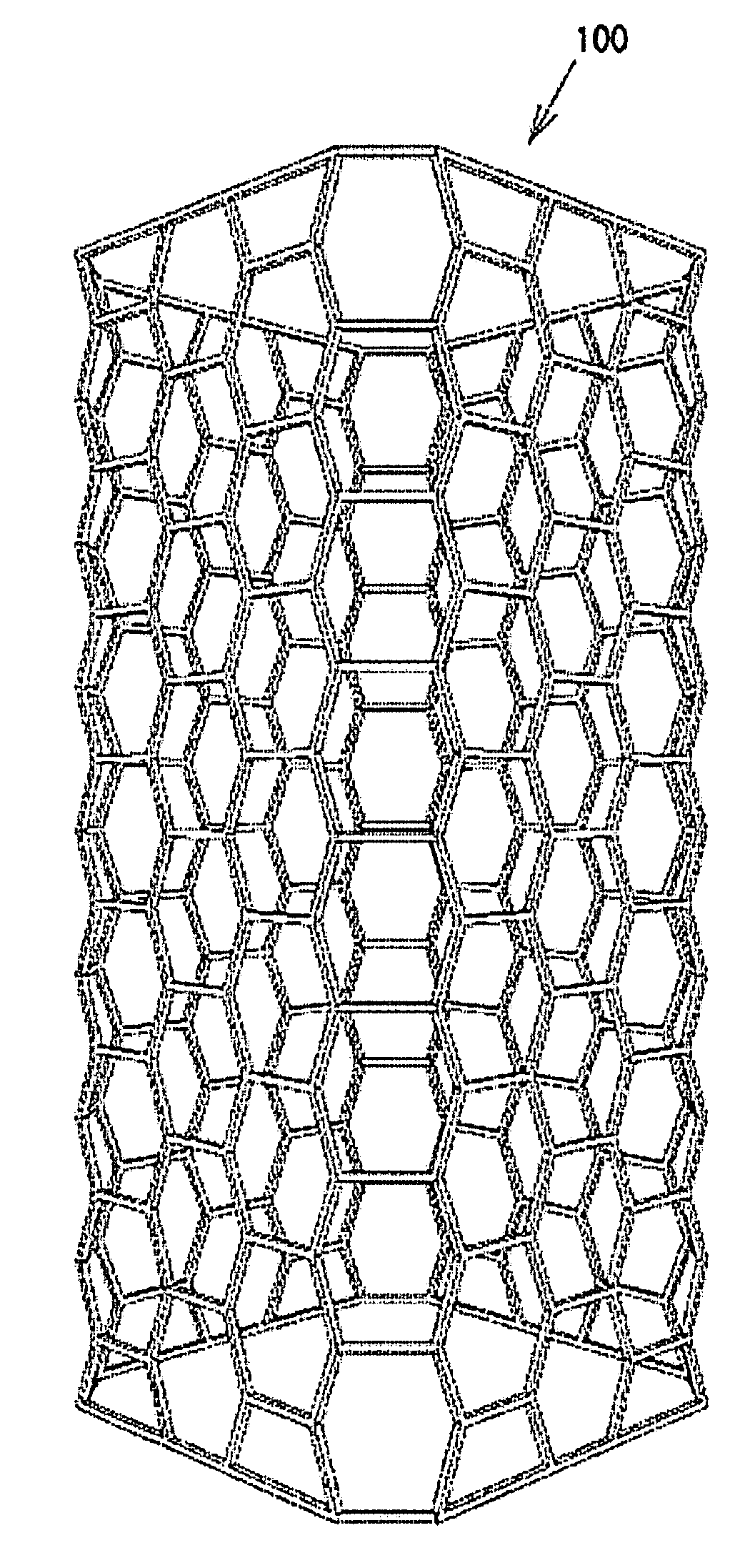
[0148]FIG. 7(A) to (C) show an example of the main frame of the architectural structure constructed by using the structural units 1 having a trifurcated shape shown in FIG. 1, (A) is a perspective overview of a tube frame 100 that serves as the main frame. (B) is an enlarged front view of a part of the tube frame 100 of FIG. 7(A). (C) is a top view.

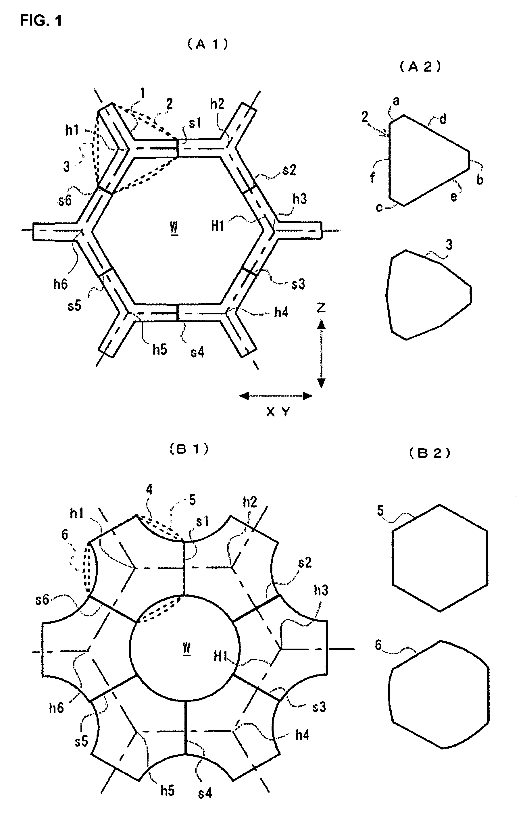
[0149]The tube frame 100 shown in FIG. 7(A) is constructed in accordance with the virtual honeycomb configuration formed from the hexagonal cells H1 as the unit cells shown in FIG. 1, and the virtual honeycomb configuration as a whole has a tubular shape. The axis of the tube extends in the vertical direction. In case the trifurcated unit 1 is used as the structural unit to be disposed on the virtual honeycomb configuration, the m...

example 2

[0186]By making reference to FIGS. 15 to 21, another example of an architectural structure having a main frame formed by connecting structural units that are disposed in a virtual honeycomb configuration will be described.

[0187]FIG. 15 is a front view showing a part of a main frame 102 of the architectural structure formed by using the structural units, for example, a part of a tube frame similar to that shown in FIG. 7(A). FIG. 16 is a partially enlarged perspective view of the main frame 102 shown in FIG. 15.

[0188]The main frame 102 shown in FIG. 15 is constructed by connecting the structural units 2 shown in FIG. 1 that are disposed for the virtual honeycomb configuration formed from the hexagonal cells H1 (indicated by thick alternate dot and dash line) as the unit cells shown in FIG. 1.

[0189]The unit 2 has a hexagonal panel with six sides as shown in FIG. 15 in front view, and has a predetermined thickness (in the direction perpendicular to the paper of drawing). In other words...

example 3

[0215]By making reference to FIGS. 22 to 25, another example of an architectural structure having a main frame formed by connecting structural units that are disposed in a virtual honeycomb configuration will be described.

[0216]FIG. 22 is a front view showing a part of a main frame 103 of the architectural structure formed by using the structural units, for example, a part of a tube frame similar to that shown in FIG. 7(A). FIG. 23 is a partially enlarged perspective view of the main frame 103 shown in FIG. 22.

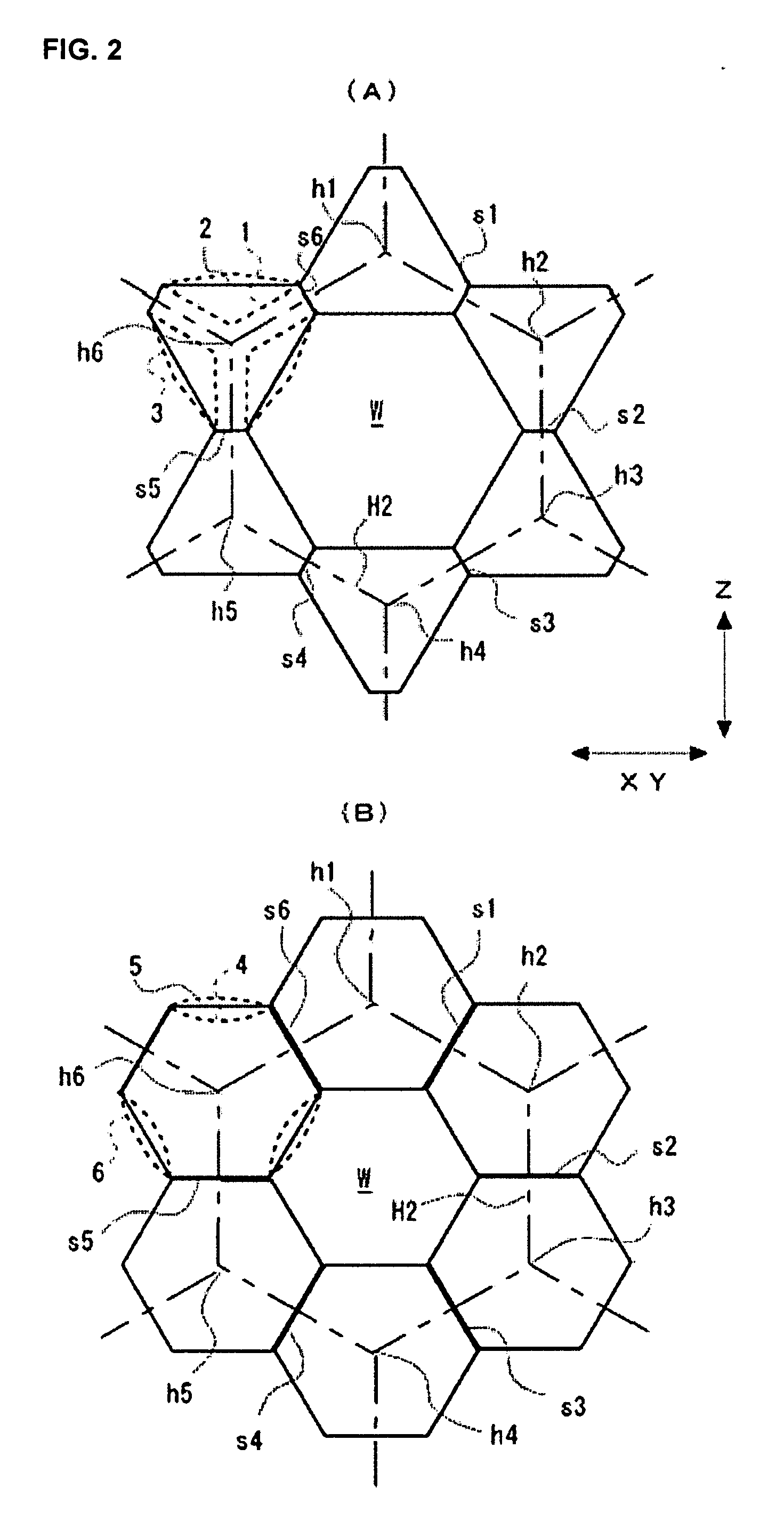
[0217]The main frame shown in FIG. 22 is constructed for the lower portion K1 by connecting the structural units 5 shown in FIG. 2 that are disposed in the virtual honeycomb configuration consisting of the hexagonal cell H2 (indicated by thick alternate dot and dash line) shown in FIG. 2, and connecting the structural units 4 shown in FIG. 2 for the upper portion K2. The unit 5 has an equilateral hexagonal panel surface as described for a modification of the unit 2 with refere...


PUM


Abstract

The present invention provides an architectural structure having a main frame of honeycomb configuration that is erected vertically and expands in a plane, a structural unit therefore, and a method for constructing the same. An architectural structure having a main frame formed by connecting a plurality of structural units, wherein a virtual honeycomb configuration that is erected vertically and expands in a plane is provided with one structural unit (1, 2, 3, 4, 5, 6) disposed at a position that includes one apex (h1, h2, h3, h4, h5, h6) of a hexagonal cell (H1, H2) that is the unit cell thereof in front view, means are provided for rigidly joining two structural units by disposing joint surfaces, that are formed in part of the respective outer circumferential surfaces of the two structural units that adjoin each other, so as to oppose each other, while the surfaces (s1, s2, s3, s4, s5, s6) that are rigidly joined each crosses one of the sides of the hexagonal cell, and an opening (W) surrounded by all the structural units that are disposed on the hexagonal cell is formed in the mid portion of each hexagonal cell.

Description

BACKGROUND OF THE INVENTION[0001]1. Field of the Invention[0002]The present invention relates to an architectural structure built by connecting a plurality of structural units with each other, and particularly to an architectural structure comprising a main frame of honeycomb configuration that expands in a plane formed from hexagonal cells as unit cells. The invention also relates to the structural unit and a method of constructing the architectural structure by using the same.[0003]2. Description of the Related Art[0004]Several methods have been known for constructing a skeleton by using structural units made of precast concrete member.[0005]Japanese Unexamined Patent Publication (Kokai) No. 9-328816 discloses a precast concrete member used in an architectural structure constructed by connecting triangular unit cells in a dome configuration, and a method of connecting the same. In the architectural structure of Japanese Unexamined Patent Publication (Kokai) No. 9-328816, six legs ...

Claims


Application Information

Patent Timeline
Patent Type & Authority Applications(United States)
IPC IPC(8): E04H12/00E04C2/40E04B1/38
CPCE04B1/18E04B2001/3583E04B1/34E04B1/22
Inventor TAKESHIMA, ICHIROKAMOSHITA, TSUTOMU
Owner SEKISUI CHEM CO LTD
Why Eureka
Try Eureka