
Tapered sleeve and fracturing head system for protecting a conveyance string

a conveyance string and tapered sleeve technology, which is applied in the field of fracturing head, can solve the problems of reducing the fracturing fluid acceleration, and reducing the fracturing head internal surface area, so as to reduce minimize or eliminate the fracturing fluid acceleration, and maximize the annular cross-sectional area

Active Publication Date: 2009-06-11
ISOLATION EQUIP SERVICES
View PDF10 Cites 27 Cited by
  • Summary
  • Abstract
  • Description
  • Claims
  • Application Information

AI Technical Summary

Benefits of technology

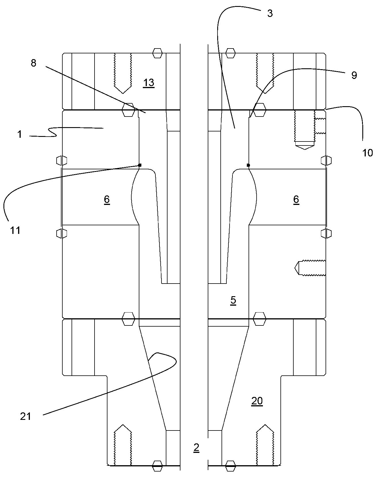
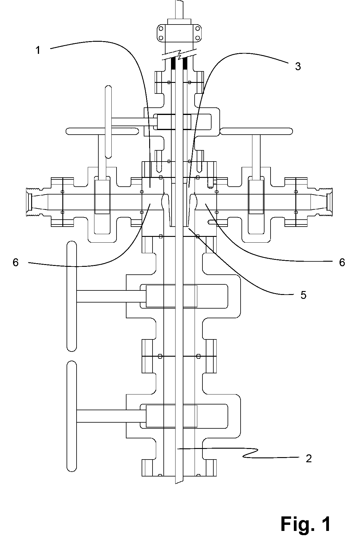
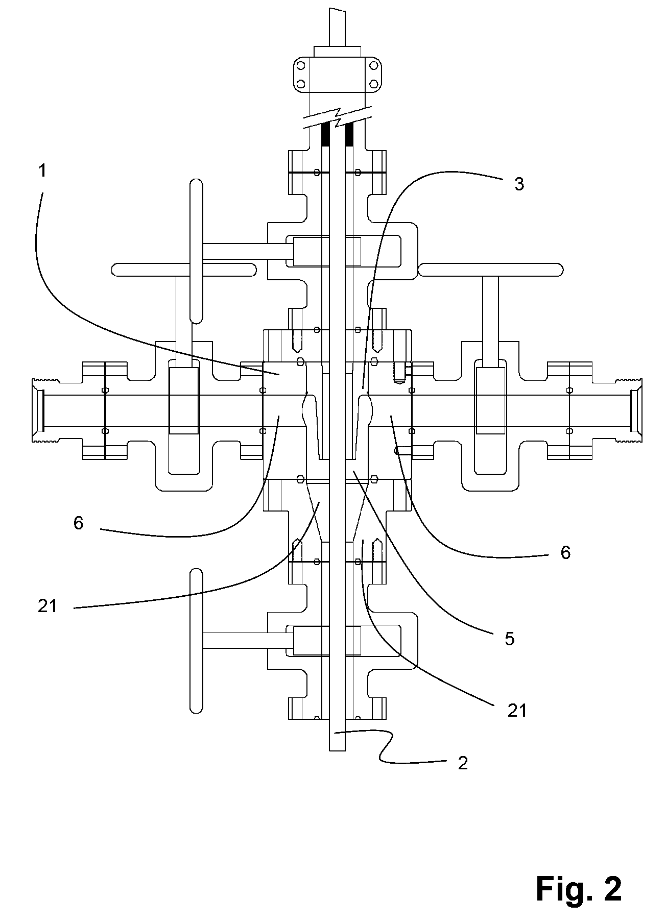
[0018]The main bore can be tapered to correspond with the tapered sleeve, thereby maximizing annular cross-sectional area for the fracturing fluid therethrough and improve fluid dynamics thereof. The main body of the fracturing head is angled or tapered to be substantially parallel to and along the length of the taper or angle of the tapered sleeve thus minimizing or eliminating fracturing fluid acceleration as the fracturing fluid travels through the annular space formed between the outer surface of tapered sleeve and the main bore of the fracturing head. The stabilized fracturing fluid travels down into the wellbore without causing abrasive damage to the conveyance string.

Problems solved by technology

However, regardless of the angle of the side ports, fracturing fluid entering the frachead is known to cause significant erosive damage to the internal surfaces of the fracturing head.
The abrasive nature of proppant in the fracturing fluid coupled with the velocity and fluid dynamics of the fracturing fluid causes erosion of the internal surfaces of the fracturing head and the conveyance string, such as coil tubing.
Higher pumping rates result in higher velocities of the fracturing fluid traveling inside the fracturing head, thereby increasing the erosive damage to the conveyance string.
Completions with fluids which vary from low erosion gels to high erosion slick water or straight water (combined with a sand proppant and nitrogen or carbon dioxide) for the fracturing fluid create much higher erosive damage.
However, the blast joint taught by Dallas only protects the coil tubing from direct impingement of the fracturing fluid and does not deflect and redirect fracturing fluid into a wellbore.
It is also known to introduce fracturing fluids through fracturing heads with angled side ports, however these fracturing heads are necessarily taller, significantly larger and heavier.

Method used


Image

  • Tapered sleeve and fracturing head system for protecting a conveyance string
  • Tapered sleeve and fracturing head system for protecting a conveyance string
  • Tapered sleeve and fracturing head system for protecting a conveyance string

Examples


Embodiment Construction

[0030]With reference to FIG. 1, a fracturing head 1 is shown fit with a tapered deflecting sleeve 3. The fracturing head 1 has a main bore 5 which receives fracturing fluid (not shown) introduced from side ports 6. The tapered sleeve intercepts the fracturing fluid, deflects and redirects the fluid downhole to a wellbore. The tapered sleeve has a sleeve bore adapted to receive a conveyance string, such as coiled tubing. By intercepting the incoming fracturing fluid, deflecting and re-directing it downhole, the tapered sleeve 3 prevents direct impingement of the fracturing fluid with the conveyance string. The fracturing fluid, which could include proppants, is deflected and redirected to avoid erosive effects of the fracturing fluid. The general deflection and redirection of the fracturing fluid downhole reduces the velocity of the fracturing fluid, as the fracturing fluid passes by the conveyance string 2, to further mitigate the erosive effects of the proppants in the fracturing f...


PUM


Abstract

A tapered sleeve and fracturing head system for introducing fracturing fluid to a wellbore, while protecting a conveyance string from the erosive effects of the fracturing fluid is disclosed. A tapered sleeve has a top portion and a tapered downhole portion. The sleeve is fit to a main bore of a fracturing head by an upset at the top portion of the sleeve that engages a shoulder of the fracturing head. The sleeve intercepts, deflects and redirects introduced fracturing fluids downhole, preventing direct impingement of the fracturing fluid against the conveyance string. The main bore of the fracturing head may also be tapered at an angle substantial parallel to and along the length of the taper of the sleeve, to further improve the fluid dynamics of the fracturing fluid and further reduce the erosive effects of the fracturing fluid.

Description

CROSS-REFERENCE TO RELATED APPLICATION[0001]This application is a regular application claiming priority of U.S. Provisional Patent Application Ser. No. 61 / 012,732 filed on Dec. 10, 2007, the entirety of which is incorporated herein by reference for all purposes.FIELD OF THE INVENTION[0002]The invention relates to improvements to a fracturing head. More particularly, a fracturing head having a tapered tubular sleeve for intercepting, deflecting, and redirecting fracturing fluid downhole, protecting a conveyance string from eroding and improving the fluid dynamics of the fracturing fluid inside the fracturing head.BACKGROUND OF THE INVENTION[0003]When completing wells that are drilled vertically, horizontally or kicked off horizontally (meaning first vertical then horizontal), several formations may be encountered. These multiple formations may be completed in one run, so as to produce fluids or gases from the multiple formations up the well to maximize the production of the several f...

Claims


Application Information

Patent Timeline
Patent Type & Authority Applications(United States)
IPC IPC(8): E21B43/26
CPCE21B43/26E21B33/068E21B43/2607
Inventor CHEREWYK BORIS (BRUCE)
Owner ISOLATION EQUIP SERVICES
Learn More