Ladder support bracket

a technology for supporting brackets and ladders, which is applied in the direction of ladders, construction, building construction, etc., can solve the problems of serious and in some instances fatal injuries, and achieve the effects of convenient positioning and actuation, simple and yet effective, and convenient attachmen

Inactive Publication Date: 2009-06-11
AVENKO
View PDF17 Cites 11 Cited by
  • Summary
  • Abstract
  • Description
  • Claims
  • Application Information

AI Technical Summary

Benefits of technology

[0007]An advantage of the present invention is to provide such a ladder support bracket which facilitates attachment to both the ladder and to an immovable structure against which the ladder is to be placed in a leaning orientation. Such immovable structure may include, but are not limited to, rain gutter, elevated floor surface, scaffoldings, roof edge, forming structure, metallic structure (L-,H-, I-beams), etc.
[0008]A further advantage of the invention is to provide a ladder support bracket which allows some relative movement of the ladder with respect to the immovable structure without compromising safe use of the ladder. To that effect, when frictionally clamped between two brackets (one on either side), any slight movement imposed to the ladder (such as oscillations of a user climbing up or down) will not tear apart or wear out the immovable structure that might not always be as solid as desired, or be more ‘fragile’ such as rain gutters. A still further advantage of the present invention is to provide a ladder support bracket comprising simple and yet effective clamps which are easy to position and actuate.
[0009]Another advantage of the present invention is to provide a ladder support bracket that can be installed / uninstalled using only one hand to allow the operator to keep his / her second hand secured to the ladder.
[0010]Yet another advantage of the present invention is to provide a ladder support bracket that can be secured to the ladder when unused to prevent lost thereof.
[0017]the second clamp being independently movable with respect to the first clamp.
[0018]Typically, the axes of the first and second clamps are generally collinear.

Problems solved by technology

It is a matter of regrettable fact that the number of accidents associated with the use of ladders is legion resulting in serious and in some instances fatal injuries.
In most if not all instances, the reason for such accidents is inadequate anchoring of the ladder when in position angled against a wall or similar structure.

Method used


Image

  • Ladder support bracket
  • Ladder support bracket
  • Ladder support bracket

Examples


Embodiment Construction

[0037]With reference to the annexed drawings the preferred embodiments of the present invention will be herein described for indicative purpose and by no means as of limitation.

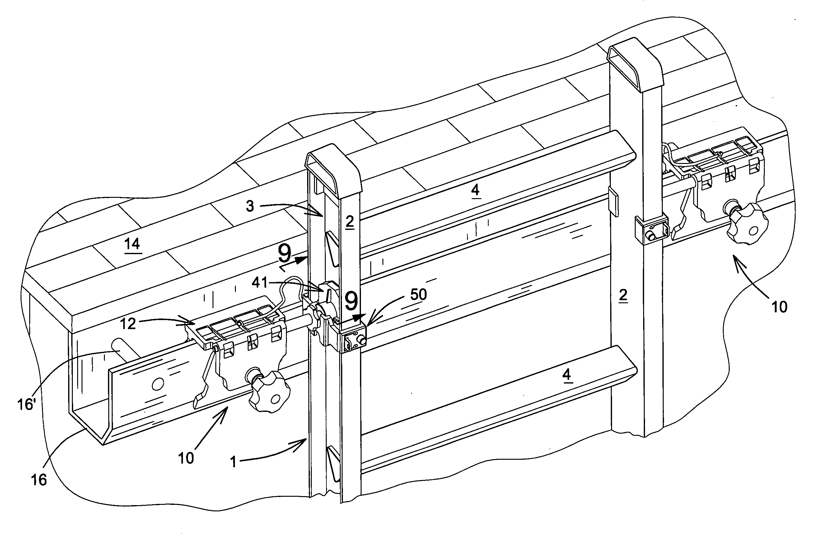
[0038]Referring to the drawings there is shown in FIG. 8 a ladder at 1 having two longitudinally extending stiles 2 of U-shaped cross section with lateral rungs 4 fixed in spaced relation along the length of the ladder 1 between the stiles 2, the ends of the rungs 4 protruding into the U-shaped space 3 of the stiles.

[0039]Typically on each side of the ladder 1, a ladder support bracket is shown generally at 10 and comprises a first clamp 12 for attachment to an immovable structure such as a wall 14 and the like and to for example roof furniture in the form of guttering shown at 16 in FIG. 8 and in ghosted outline in FIG. 6.

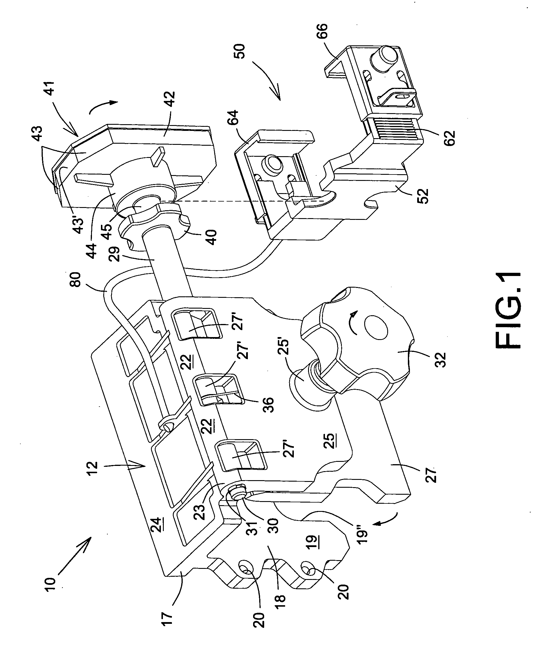
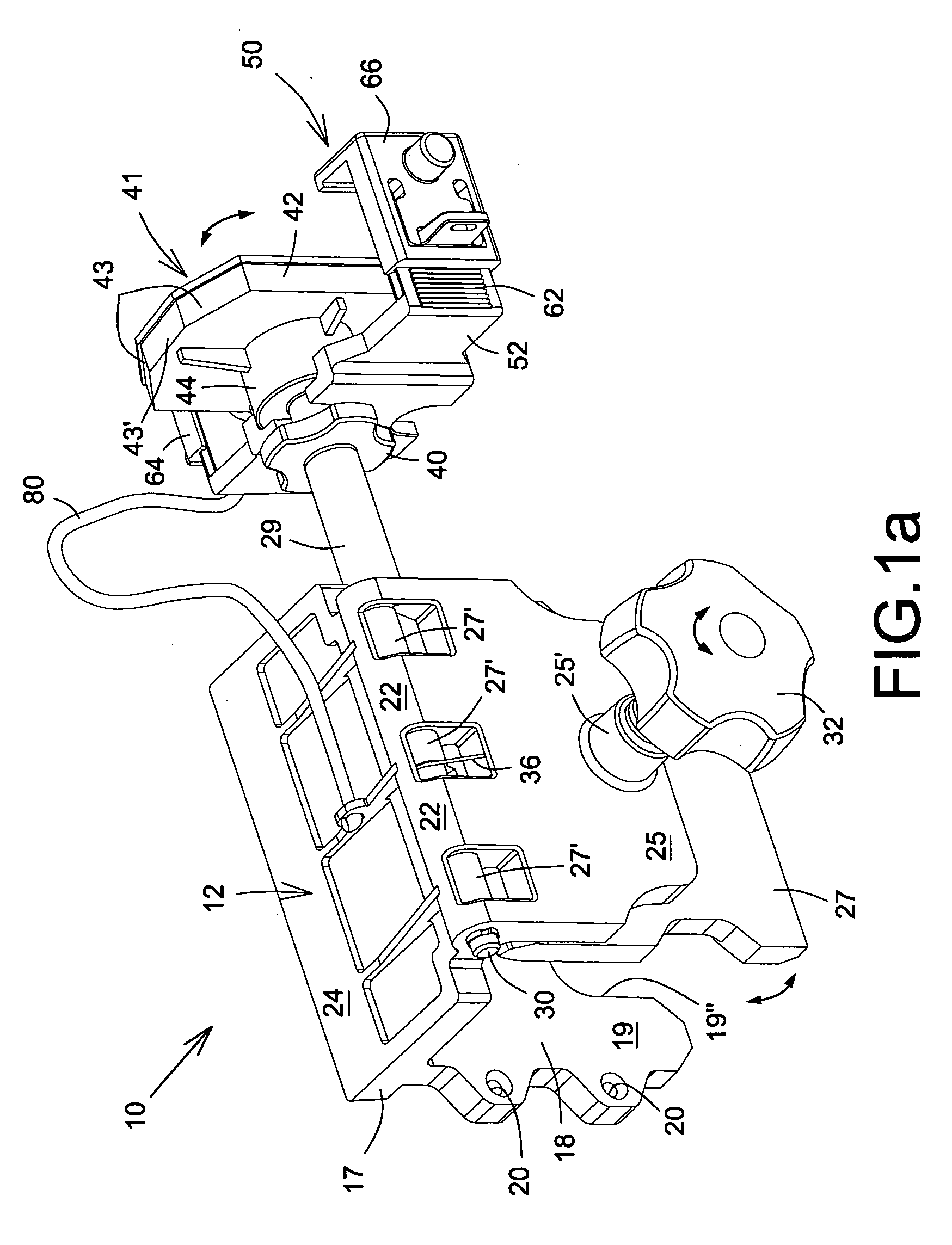
[0040]As shown in FIGS. 1 and 1a, the clamp 12 comprises a U-shaped mounting plate 18 having one wall 19 provided with fixing holes 20 for bolts, screws or the like (not shown), to secure t...


PUM


Abstract

A ladder support bracket comprises a first clamp for clamping to an immovable structure connected to a second clamp for clamping to the ladder stile, the first clamp having a fixed and moveable jaw moving on a hinge shaft, and the second clamp comprising a clamping pad mounted on the hinge shaft distally from the first clamp for frictional engagement with the ladder stile upon rotation of the pad.

Description

FIELD OF THE INVENTION[0001]The present invention relates to a ladder support bracket for providing a safe mounting arrangement for a ground-engaging ladder when propped up against a building.BACKGROUND OF THE INVENTION[0002]It is a matter of regrettable fact that the number of accidents associated with the use of ladders is legion resulting in serious and in some instances fatal injuries. In most if not all instances, the reason for such accidents is inadequate anchoring of the ladder when in position angled against a wall or similar structure.[0003]Many and varied arrangements have been proposed for stabilizing the ladder in its use position. For example, legs attached to the stiles of the ladder have been suggested for additional contact with the ground to give more stability and struts for contact with the supporting wall have also been used.[0004]A more specific type of ladder support finds form in a bracket attachable at the upper end of the ladder with a clamp for positive en...

Claims


Application Information

Patent Timeline
Patent Type & Authority Applications(United States)
IPC IPC(8): E06C7/06
CPCE06C7/486
Inventor ARSENEAULT, DANIELPERREAULT, DANIEL
Owner AVENKO
Why Eureka
Try Eureka