
Ground fault detection and localization in an ungrounded or floating DC electrical system

a technology of ground fault and electrical system, which is applied in the direction of emergency protective arrangements for limiting excess voltage/current, testing circuits, instruments, etc., can solve the problems of stray capacitive coupling between system conductors and adjacent grounded surfaces, process disruption and safety hazards, and disruption of the entire power system

Inactive Publication Date: 2009-06-11
HONEYWELL INT INC
View PDF7 Cites 29 Cited by
  • Summary
  • Abstract
  • Description
  • Claims
  • Application Information

AI Technical Summary

Problems solved by technology

A disadvantage of a grounded system lies in the fact that even a single line-ground fault may lead to heavy fault currents and hence disrupt operation of the entire power system.
Ground faults can lead to process disruption and safety hazards such as equipment malfunctions, fire and electric shock.
However, in any system, stray capacitive coupling may exist between the system conductors and adjacent grounded surfaces.
However in the event of a line-ground fault in an ungrounded system, the voltage of the healthy phases may rise to line-to-line voltage.
Thus voltage stress on the healthy phase conductors may increase during fault condition.
Further, there may be capacitive voltage build up if the fault is of restriking nature.
Also, due to increased voltage stress, the probability of occurrence of second line to ground fault may increase.
Though a single line to ground fault may not impact operation of an ungrounded system, a second ground fault may lead to phase-to-phase fault, with very high fault current.
In the event of such a phase-to-phase fault, power interruption is required, thus leading to system outage.
However, these methods fail to indicate the localization of the ground fault.
However, this procedure leads to unnecessary disconnection of power sources or loads, disrupting the system operation.

Method used


Image

  • Ground fault detection and localization in an ungrounded or floating DC electrical system
  • Ground fault detection and localization in an ungrounded or floating DC electrical system
  • Ground fault detection and localization in an ungrounded or floating DC electrical system

Examples


Embodiment Construction

[0025]The following detailed description is of the best currently contemplated modes of carrying out the invention. The description is not to be taken in a limiting sense, but is made merely for the purpose of illustrating the general principles of the invention, since the scope of the invention is best defined by the appended claims.

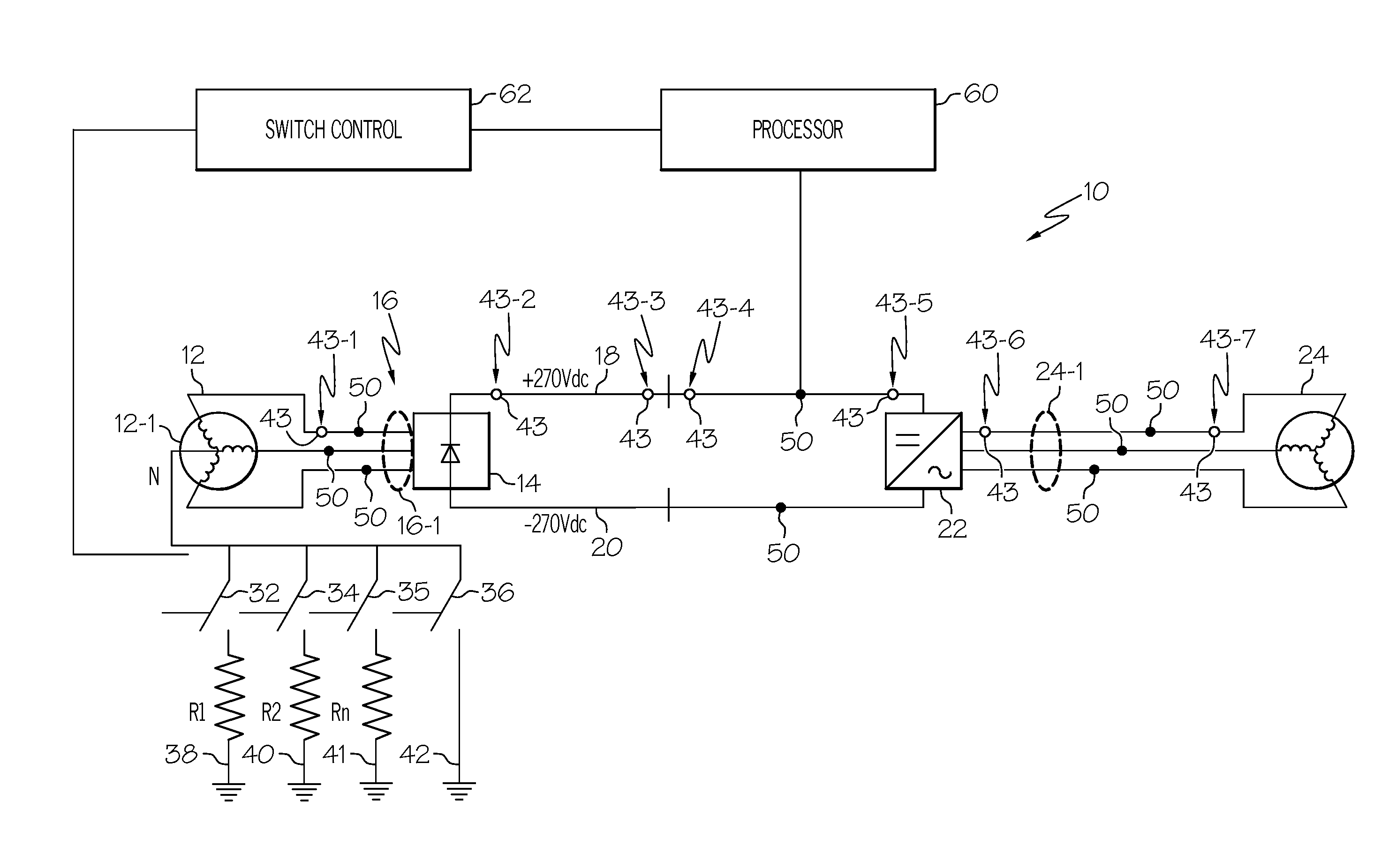
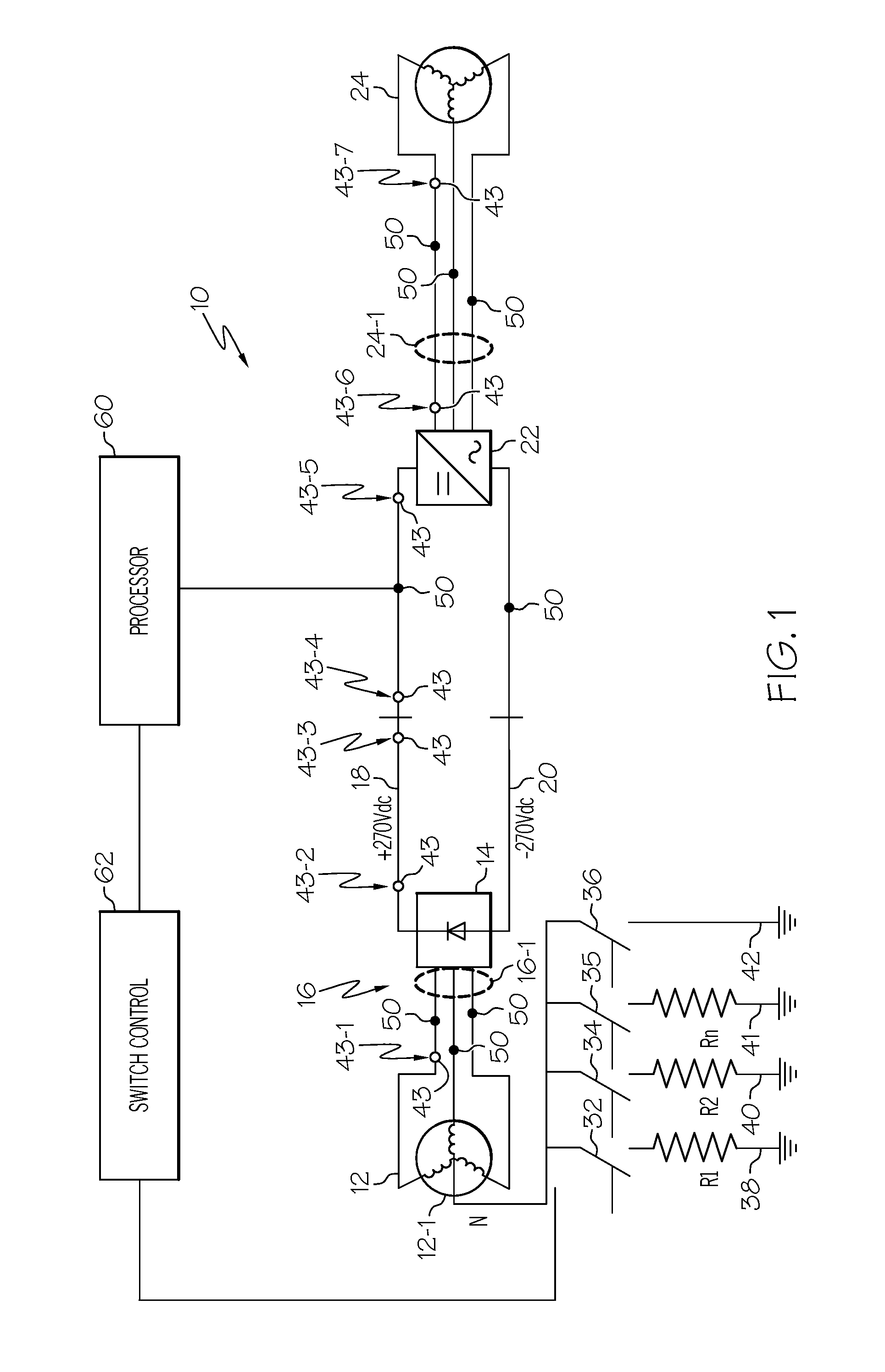
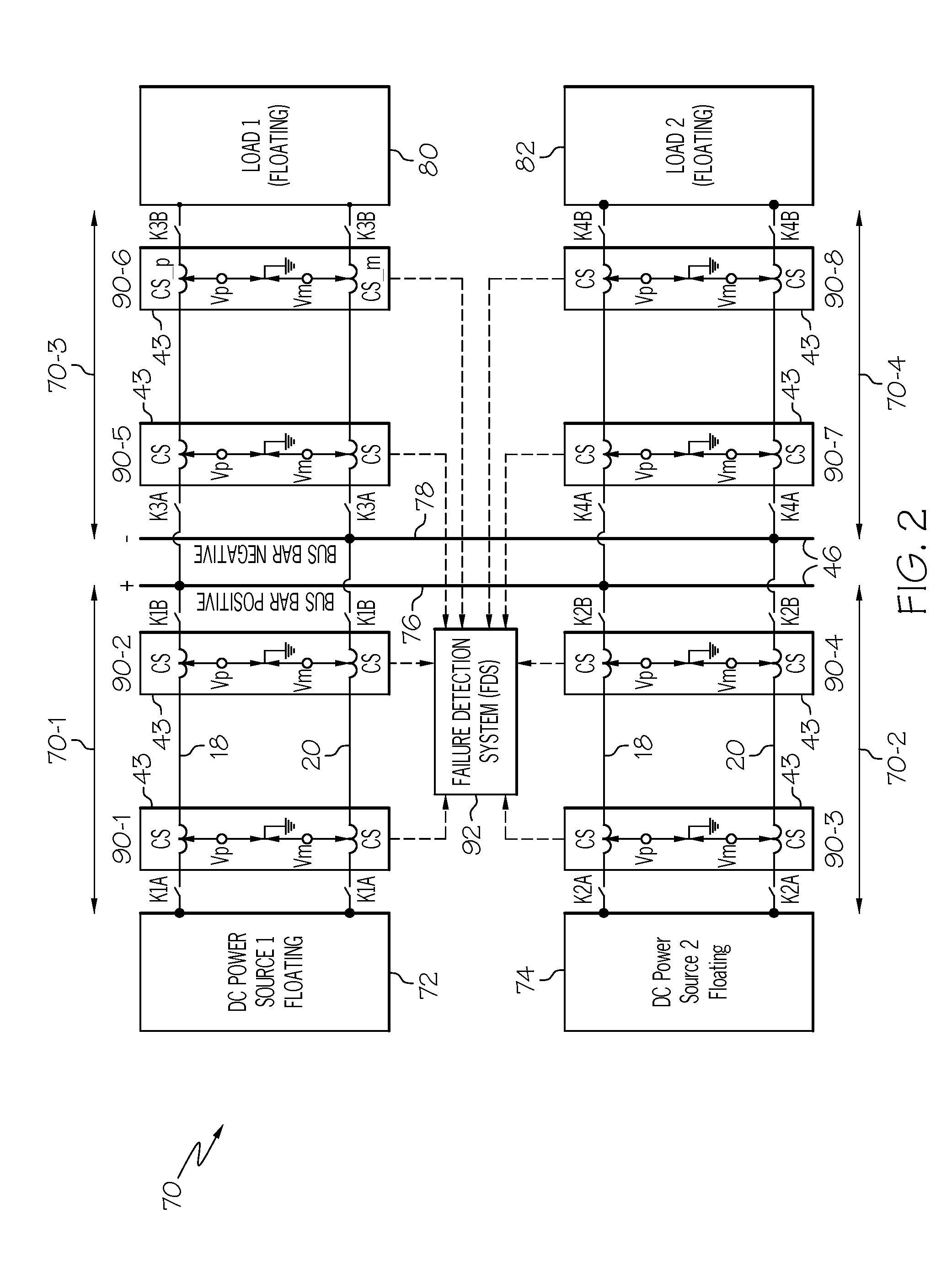
[0026]The present invention provides a system for detection and isolation of ground faults in an ungrounded or floating DC electrical power distribution system or network.

[0027]The inventive system may gradually ground an ungrounded system in a controlled manner for early detection and isolation of a single line-ground fault. Additionally the inventive system may provide localization of a single ground fault in a complex floating network. The invention may be useful in any ungrounded commercial power system and more particularly in aerospace electrical power system application.

[0028]In contrast to the prior art, which may use sequential disconnection of...


PUM


Abstract

An ungrounded or floating DC electrical power distribution system may experience a single line to ground fault. Such a fault may not disrupt operation of the system, but its presence may raise a risk of additional problems if left uncorrected. A system for progressively grounding the ungrounded system may be initiated when a line to ground fault is suspected based on the voltage difference measured to a common chassis point. As grounding through successively lower impedance proceeds, fault current may increase and detection of severity of the line to ground fault may be more readily achieved, thus facilitating localization of the fault. Localization may be achieved through an analysis of direction of capacitive currents in isolatable zones of the system.

Description

RELATED APPLICATIONS[0001]The present application claims benefit of U.S. Provisional Application 60992752 filed Dec. 6, 2007.BACKGROUND OF THE INVENTION[0002]The present invention generally relates to apparatus and methods for providing protection for an electrical system and, more particularly, to apparatus and methods of ground fault detection in an ungrounded electrical system.[0003]In a grounded three phase alternating current (AC) electric power system a neutral point may be connected to ground (or chassis ground). In a grounded direct current (DC) power system, either a positive or a return conductor may be grounded. In some cases, a middle point of a DC voltage source may be grounded.[0004]A grounded system may be grounded solidly or through some impedance. Grounding through an impedance may help in controlling a level of fault current arising out of a single line-ground fault. An ungrounded system does not have any direct connection to the ground. In other words, the groundi...

Claims


Application Information

Patent Timeline
IPC IPC(8): H02H9/08G01R31/14
CPCH02H9/08G01R31/025G01R31/52
Inventor LAZAROVICH, DAVIDDANGETI, SRINIVASA RAOKESHRI, SUBODHRUSAN, ILEANACHAUDHARY, SANJAY KUMAR
Owner HONEYWELL INT INC
Learn More