Film camera head

a camera head and film technology, applied in the field of camera heads, can solve the problems of brusque movements, camera movements accompanied by jerky movements, and the task of trying to provide the stability that is nowadays demanded from film cameras,

Inactive Publication Date: 2009-06-11
VALLES NAVARRO ANDRES +1
View PDF3 Cites 19 Cited by
  • Summary
  • Abstract
  • Description
  • Claims
  • Application Information

AI Technical Summary

Problems solved by technology

The problem of the type of devices such as the one described above is that they are quite rigid and on account of their weight have elevated inertia, thereby making it fruitless the task of trying to provide the stability that is nowadays demanded from film cameras.
Moreover, they suffer the consequences of the vibrations to which the support of the assembly is subjected, which in turn causes instability while filming.
Filming instability arises, on other occasions, either from the very movement of the camera, which is supported on means that are in motion, such as, in travelling shots, in car scenes, in helicopter scenes, etc, with the ensuing changes and variations in the vertical inclination and in the lateral angle of the filming, or also from the movement of the object that is being filmed, the result of this all being erratic and brusque movements of the shooting frame, shaking, etc.
The high inertia of the frames of the known art may cause camera movements to be accompanied by jerky movements that may produce vibrations.
These vibrations are corrected by suppressing the sensibility of the electronics that control the movements on the respective axle, this resulting in a loss of accuracy.
Finally, the very inertia and thrusting of the camera supports cause the maladjustment of the electronic system that controls the movement on each axle after a break or a long period of non-use, making it necessary to recalibrate said system before using the camera again.
It is to be noted that even the slightest delays in the calibration of compensating mechanisms for cameras and, in general, getting said camera ready for use, represent elevated costs in an industry like the film-making industry, which gets many professionals and specialists on the move during the process of filming.

Method used


Image

  • Film camera head
  • Film camera head
  • Film camera head

Examples


Embodiment Construction

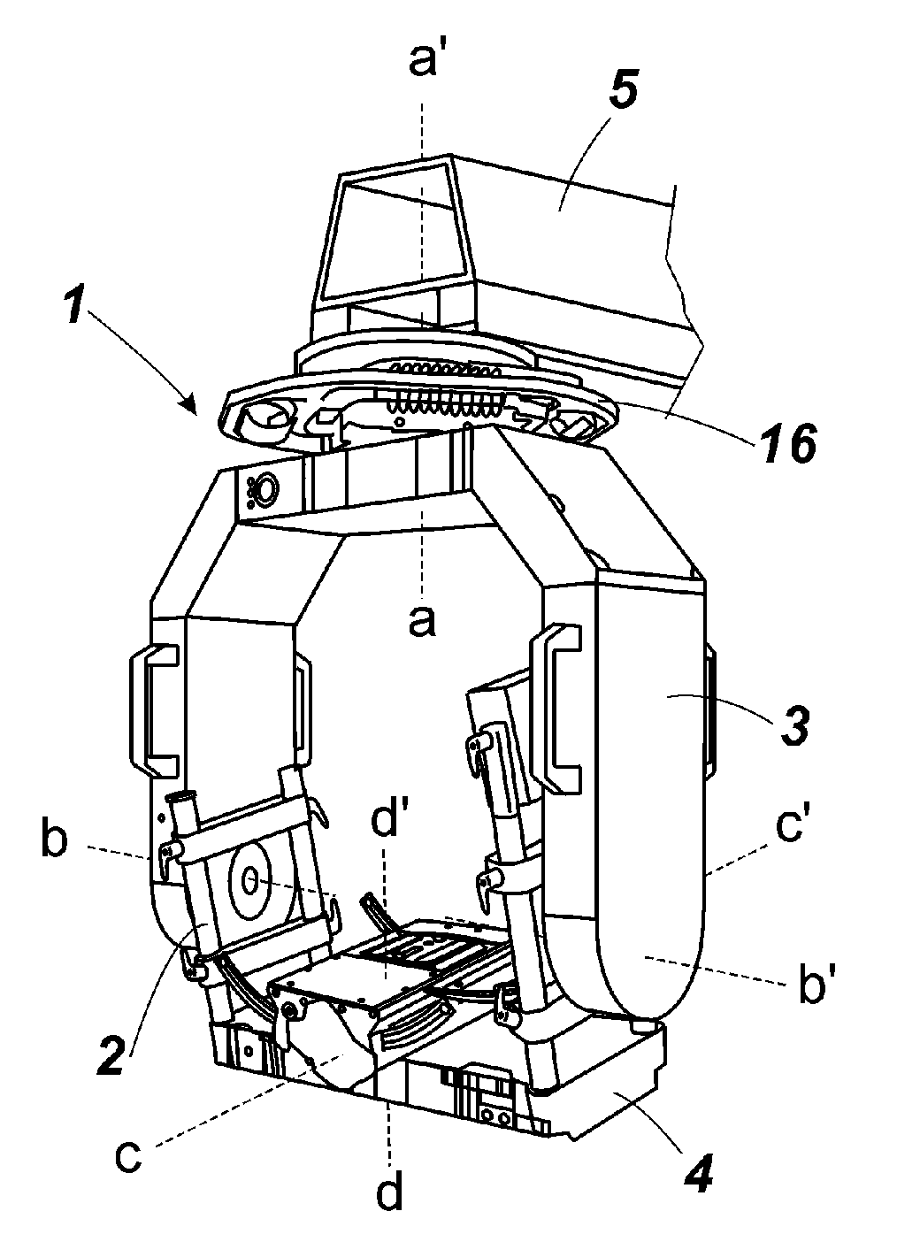
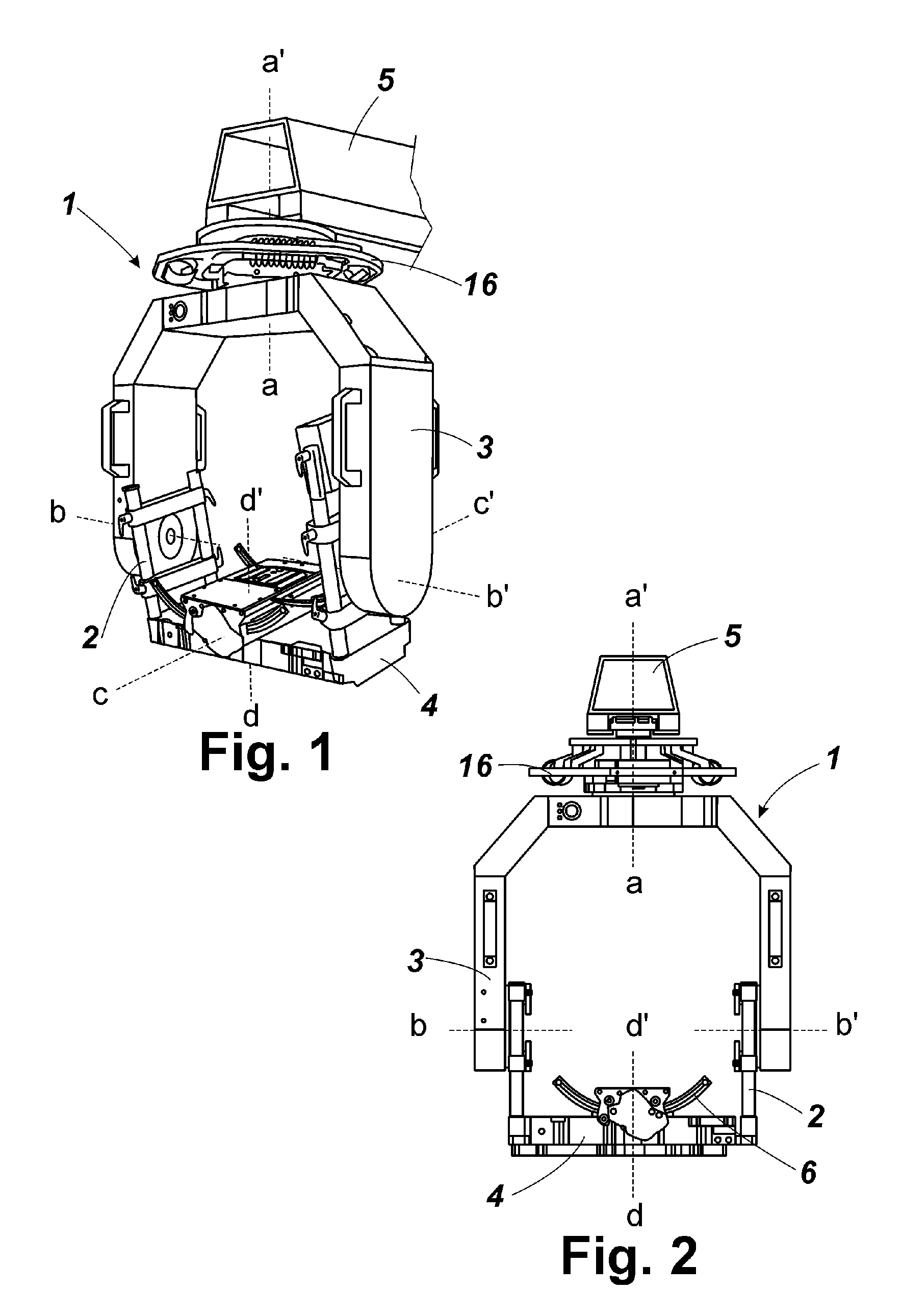
[0021]The present invention discloses a stabilized head for film cameras that comprises a frame provided with damping means for the joining of said head to its support through a progressive inertia-reducing unit, so that a distribution connecting rod progressively reduces the impact resulting from the movement of the film camera.

[0022]All the above is combined with a damping means provided with resilient springs for isolating the head from external vibrations.

[0023]Additionally, it has been developed an independent movement for correction of the undesirable movements of the head. The PAN control supports the TILT control axle, which in turn supports a correction axle. It is this correction axle the one that supports the ROLL movement control.

[0024]The most direct result of said independent correction of undesirable head movements is that the correction of the vibrations does not affect panoramic movement. Within the PAN movement itself, the PAN axle carries out the panoramic movemen...


PUM


Abstract

HEAD FOR FILM CAMERAS, of the type that comprises a supporting frame with means for automated and remotely controlled movement about three orthogonal axles aa′, bb′, cc′, said head (1) frames comprising two “U”'s, one of them being secondary (2) and rotating about the TILT axle bb′, and the other being a main “U” (3) and rotating about the PAN axle aa′, said “U” facing one another and being articulatedly joined, the base of said secondary “U” (2) having a swinging crosspiece (4) that on its inner face supports a curve guide (6) for fixing and supporting that film camera, which curve guide (6) provides rotation along the ROLL axle cc′, said head (1) being joined to its support (5) with resilient damping means against undesirable movements and vibrations of said support (5) and in addition to the known movement axles, namely, PAN aa′, TILT bb′ and ROLL cc′, said head (1) is provided with an independent correcting axle dd′ having means for performing a correcting movement in the opposite direction to the undesirable movements of the PAN axle aa′.

Description

FIELD OF THE INVENTION[0001]The present invention discloses a camera head for filming of the type that permits freedom of movement of same about three orthogonal axles, with the distinctive feature that it incorporates damping means against the vibrations to which said head may be subject, said head having a control for additional movement that is independent of the head for correction of undesirable movements.PRIOR ART[0002]It is known in the art related to this field of business that there exist three possible film camera movements in relation to the three orthogonal axles that comprise our field of view.[0003]In the first place, PAN movements (panoramic) occur when the camera is horizontally displaced, this resulting in a movement either to the right or to the left relative to the shooting frame.[0004]TILT movements are equivalent to vertical displacements of the shooting that result in upward and downward movements of the image with respect to the horizon.[0005]Lastly, ROLL move...

Claims


Application Information

Patent Timeline
Patent Type & Authority Applications(United States)
IPC IPC(8): G03B17/00F16M13/00
CPCF16M11/04F16M11/041F16M11/105F16M11/12G03B17/56F16M11/2064F16M13/00F16M2200/068F16M11/18G03B17/561
Inventor VALLES NAVARRO, ANDRESVALLES NAVARRO, ALFREDO
Owner VALLES NAVARRO ANDRES
Why Eureka
Try Eureka