Connector

a technology of connecting rods and connecting rods, applied in the field of connecting rods, can solve the problems of preventing the connection operation and complicating the connection operation, and achieve the effects of simple structure, improved operability, and easy adjustment of the posture of the second housing during the connection operation

Active Publication Date: 2009-06-11
SUMITOMO WIRING SYST LTD
View PDF19 Cites 5 Cited by
  • Summary
  • Abstract
  • Description
  • Claims
  • Application Information

AI Technical Summary

Benefits of technology

[0009]It is sufficient to adjust the posture of the second housing at an initial stage of a connecting operation so that the first rib and the first groove engage. Adjusting the posture of the second housing is easier and operability is better as compared with the case where the posture of the second housing is adjusted for simultaneously establishing the engagement of the first rib and the first groove and the engagement of the second rib and the second groove.
[0010]The connection of the housings progresses with the first rib and the first groove engaged. The posture of the second housing then is adjusted to engage the second rib and the second groove. However, at this time, the second housing already is fit in the receptacle and the posture of the second housing is substantially correct. Therefore, adjusting the posture of the second housing during the connecting operation is easy.
[0011]The second rib may project from the first rib, and the second groove may be recessed in the first groove. The shapes of these structures are simpler as compared with the case where the first and second ribs project independently and the first and second grooves are recessed independently.

Problems solved by technology

However, the outer surface of the second housing interferes with the rib to prevent connection if the second housing is in an incorrect posture.
However, the connecting operation is not prevented when the receptacle is inclined about an axis parallel to the longer sides of the receptacle.
This complicates the connecting operation.

Method used


Image

  • Connector
  • Connector
  • Connector

Examples


Embodiment Construction

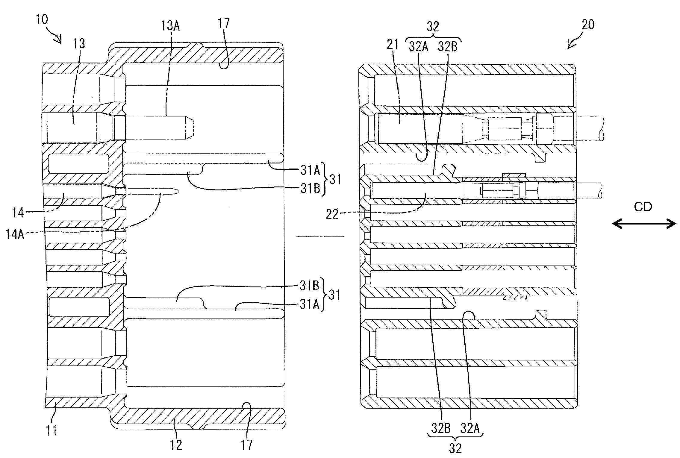
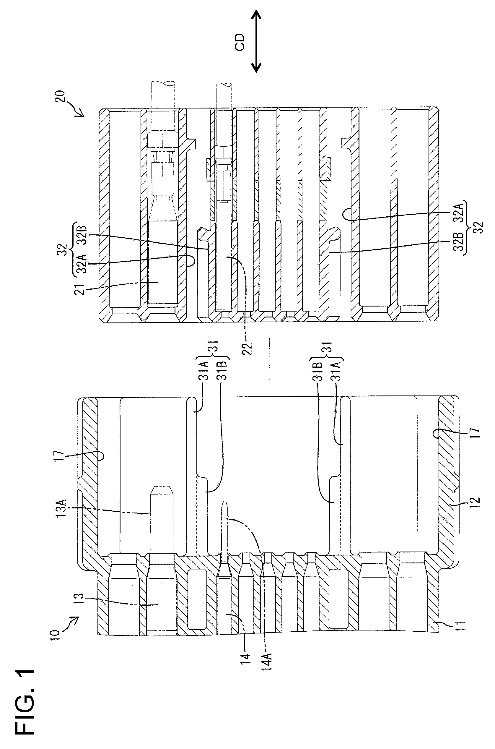
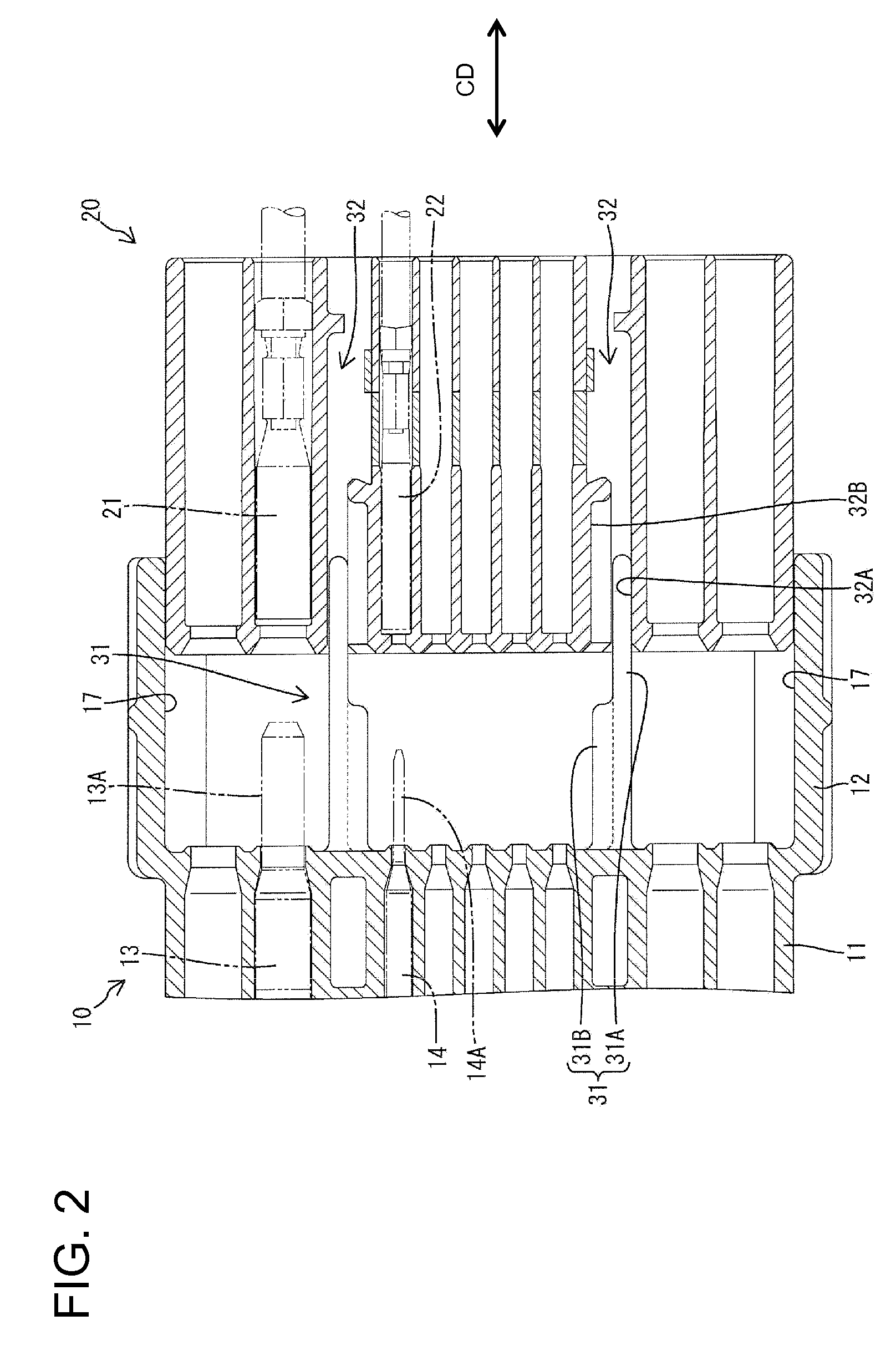
[0029]A connector in accordance with the invention is described with reference to FIGS. 1 to 9. The connector has a first housing 10 and a second housing 20 connectable with and separable from each other along the connecting direction CD. In the following description, connecting ends of the respective housings 10, 20 are referred to as front ends concerning forward and backward or connecting direction CD.

[0030]The first housing 10 is made unitarily e.g. of synthetic resin and has a wide block-shaped terminal accommodating portion 11 and a wide rectangular tubular receptacle 12 extends forward from the outer periphery of the terminal accommodating portion 11. Main bodies of large male terminal fittings 13 and small male terminal fittings 14 are accommodated in the terminal accommodating portion 11. Large tabs 13A at the front ends of the large male terminal fittings 13 and small tabs 14A at the front ends of the small male terminal fittings 14 project into the receptacle 12 from the ...


PUM


Abstract

A restriction (30) is provided for preventing a second housing (20) from being fit in an incorrect oblique posture into a receptacle (12). The restriction includes restricting ribs (31) projecting from an inner surface of the receptacle (12) and restricting grooves (32) formed by recessing an outer surface of the second housing (20). Each restricting rib (31) includes a first rib (31A) extending in a connecting direction and second ribs (31B) located behind the front end of the first rib (31A) in the connecting direction. Each restricting groove (32) includes a first groove (32A) extending in the connecting direction and second grooves (32B) located before the rear end of the first groove (32A) in the connecting direction.

Description

BACKGROUND OF THE INVENTION[0001]1. Field of the Invention[0002]The invention relates to a connector.[0003]2. Description of the Related Art[0004]U.S. Pat. No. 7,214,090 discloses a connector with first and second housings. The first housing has a receptacle and the second housing is configured to fit in the receptacle. The connector also has a restriction for preventing the second housing from being fit in an incorrect posture. The restriction includes a rib formed on an inner surface of the receptacle and a groove formed in an outer surface of the second housing. The rib and the groove engage to permit a connecting operation of the housings when the second housing is fit into the receptacle in a correct posture. However, the outer surface of the second housing interferes with the rib to prevent connection if the second housing is in an incorrect posture.[0005]The restricting rib of the above-described conventional connector projects substantially at right angles from a longer side...

Claims


Application Information

Patent Timeline
Patent Type & Authority Applications(United States)
IPC IPC(8): H01R13/64
CPCY10S439/948H01R13/6456H01R13/639H01R13/46
Inventor TAKEDA, KAZUAKI
Owner SUMITOMO WIRING SYST LTD
Why Eureka
Try Eureka