Modular lateral expansion device

a lateral expansion and module technology, applied in the field of medical devices, can solve the problems of poor placement and subsidence of implants, difficult surgically to seat intervertebral body devices sufficiently laterally to capture and utilize this portion of bone, and implant failur

Inactive Publication Date: 2009-06-11
CUSTOM SPINE INC
View PDF4 Cites 28 Cited by
  • Summary
  • Abstract
  • Description
  • Claims
  • Application Information

AI Technical Summary

Benefits of technology

[0012]The second end further comprises a hole dimensioned and configured to permit insertion means to grip and remove the apparatus into the vertebral body. The first lateral portion includes a plurality of cuts. The second lateral portion includes a first slot positioned at an edge of the second lateral portion and a second slot positioned in a substantially central area of the second lateral portion. The top wall includes a top ridge and a top contour surface and the bottom wall includes a bottom ridge and a bottom contour surface. The top ridge and the bottom ridge are inwardly angled into the second lateral portion and flank the second slot. The top ridge and the bottom ridge may be positioned opposite to each other and adapted to provide torsional stability for PLIF insertion of the lateral member into the vertebral body. The top contour surface and the bottom contour surface may be dimensioned and configured to accommodate an angled anatomy of a vertebral endplate.

Problems solved by technology

Due to variable soft tissue anatomy, it is often difficult surgically to seat intervertebral body devices sufficiently laterally to capture and utilize this portion of bone.
Thus, poor placement and subsidence of implants can occur leading to implant failure and diseases of the spine such as kyphosis (e.g., a curvature of the upper spine which can be either the result of bad posture or a structural anomaly in the spine), lordosis (e.g., an inward curvature of a portion of the vertebral column) and foraminal stenosis (e.g., narrowing of vertebral foramen).
Implant failure can and does lead to catastrophic clinical failure and exceedingly difficult and potentially dangerous spinal revision strategies.
These implants usually do not violate the vertebral endplate but do not reliably reach the outermost structurally significant area of bone.
Cages also require destruction of the vertebral endplate by tapping or cutting the structural bone, thus leading to a greater rate on implant subsidence and foraminal stenosis.

Method used


Image

  • Modular lateral expansion device
  • Modular lateral expansion device
  • Modular lateral expansion device

Examples


Embodiment Construction

[0021]The embodiments herein and the various features and advantageous details thereof are explained more fully with reference to the non-limiting embodiments that are illustrated in the accompanying drawings and detailed in the following description. Descriptions of well-known components and processing techniques are omitted so as to not unnecessarily obscure the embodiments herein. The examples used herein are intended merely to facilitate an understanding of ways in which the embodiments herein may be practiced and to further enable those of skill in the art to practice the embodiments herein. Accordingly, the examples should not be construed as limiting the scope of the embodiments herein.

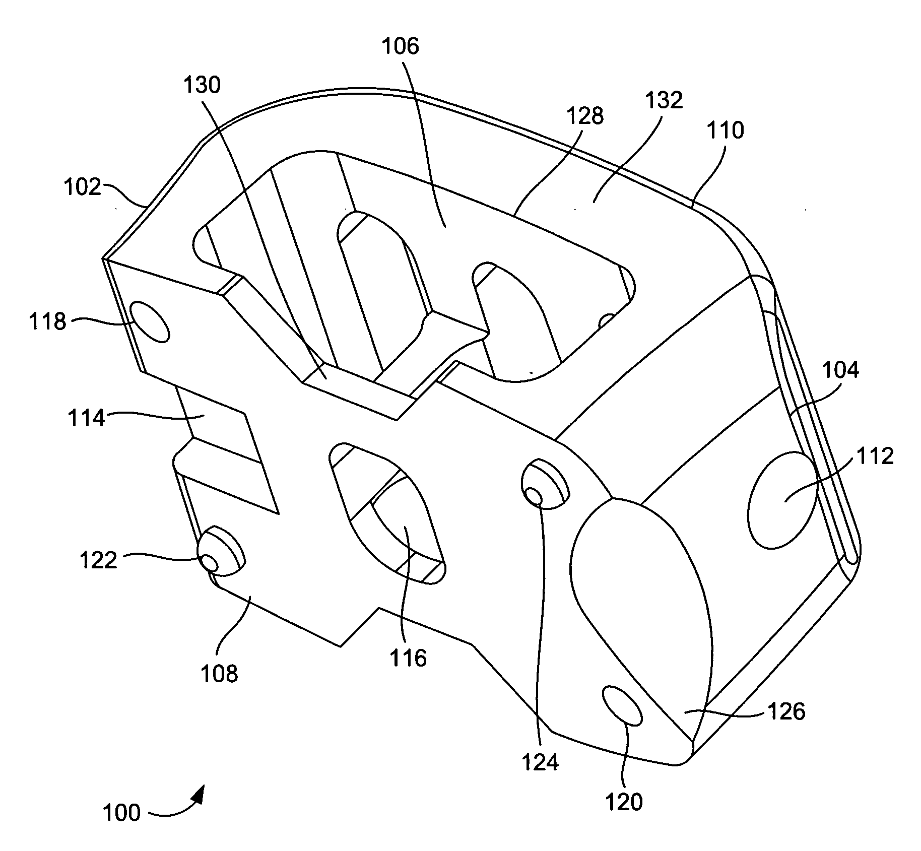
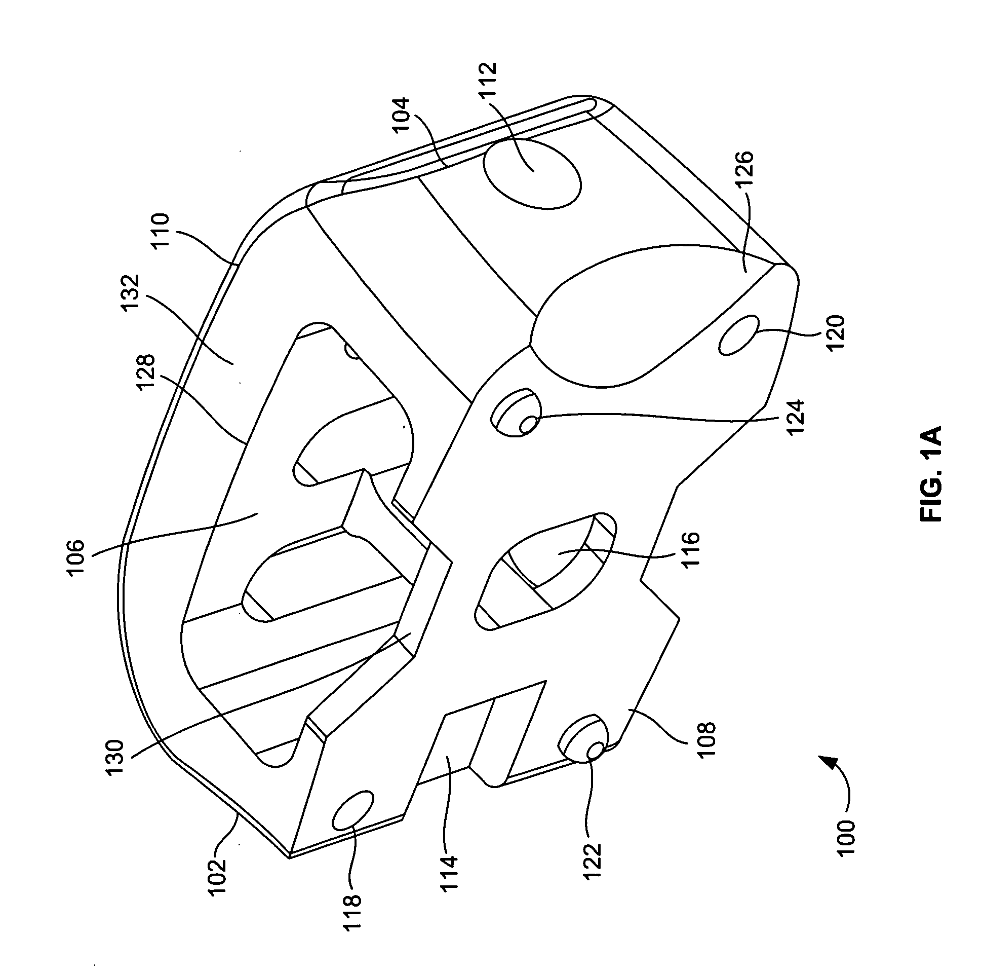
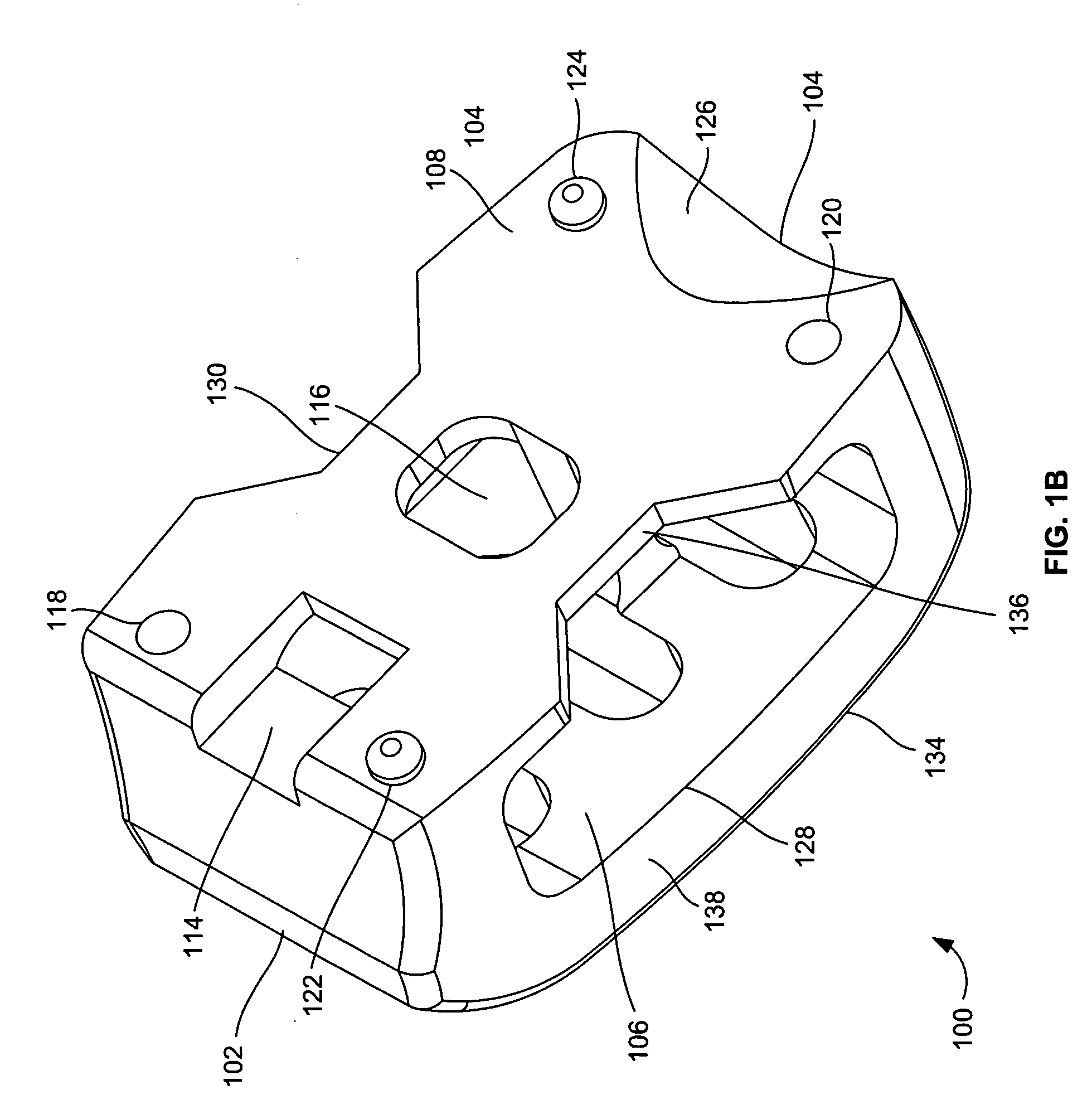
[0022]As mentioned, there remains a need for a new modular lateral expansion device for placing between vertebral bodies within the vertebral body both in lateral and cephalocaudal directions for enhanced structural support of the spine. The embodiments herein achieve this by providing a modula...


PUM


Abstract

A modular lateral expansion device to be inserted into a vertebral body. The modular lateral expansion device comprises a pair of complementary lateral members. Each of the lateral members includes a first end, a second end, a first lateral portion, a second lateral portion, a top wall, a bottom wall, and a cavity configured through the top wall and the bottom wall. The top wall includes a top ridge and a top contour surface and the bottom wall includes a bottom ridge and a bottom contour surface. The top ridge and the bottom ridge are inwardly angled into the second lateral portion. The first lateral portion includes a plurality of cuts. The second lateral portion includes a first slot positioned at an edge of the second lateral portion and a second slot positioned in a substantially central area of the second lateral portion.

Description

BACKGROUND[0001]1. Technical Field[0002]The embodiments herein generally relate to medical devices, and, more particularly, to a modular lateral expansion device used during orthopedic surgeries.[0003]2. Description of the Related Art[0004]In lumbar interbody spinal fusion procedures, two adjacent vertebral bodies are fused together by entirely or partially removing the degenerated intervertebral disc between two adjacent vertebrae and inserting an implant within the vertebral body. Lastly, fusion material (e.g., bone graft) may be placed within the vertebral body which along with the body's natural cells promotes bone formation.[0005]The greatest compressive strength in the spine lies within the outer 30% of the vertebral bodies. Due to variable soft tissue anatomy, it is often difficult surgically to seat intervertebral body devices sufficiently laterally to capture and utilize this portion of bone. Thus, poor placement and subsidence of implants can occur leading to implant failu...

Claims


Application Information

Patent Timeline
Patent Type & Authority Applications(United States)
IPC IPC(8): A61B17/58A61F2/44
CPCA61B17/70A61B17/8858A61F2/30965A61F2/447A61F2002/30354A61F2310/00131A61F2002/30785A61F2002/30789A61F2002/4475A61F2002/448A61F2310/00023A61F2002/30604A61F2002/30593
Inventor BURD, TIMOTHY A.ABDELGANY, MAHMOUD F.
Owner CUSTOM SPINE INC
Why Eureka
Try Eureka