Prosthetic device and system for preparing a bone to receive a prosthetic device

Active Publication Date: 2009-06-11
MAKO SURGICAL CORP
View PDF17 Cites 197 Cited by
  • Summary
  • Abstract
  • Description
  • Claims
  • Application Information

AI Technical Summary

Benefits of technology

[0009]According to an aspect of the present invention, a substantially cup-shaped prosthetic device for a joint includes an outer surface configured to operatively engage at least one of a first bone of the joint and a component and an inner surface configured to connect to a second bone of the joint. The inner surface is rotationally asymmetric to minimize intrusion on a vascular region of the second bone.
[0010]According to another as

Problems solved by technology

Over time, the hip joint 10 may degenerate (for example, due to

Method used


Image

  • Prosthetic device and system for preparing a bone to receive a prosthetic device
  • Prosthetic device and system for preparing a bone to receive a prosthetic device
  • Prosthetic device and system for preparing a bone to receive a prosthetic device

Examples


Embodiment Construction

[0036]Presently preferred embodiments of the invention are illustrated in the drawings. An effort has been made to use the same or like reference numbers throughout the drawings to refer to the same or like parts.

[0037]FIGS. 4A through 4F show an embodiment of a prosthetic device 5 according to the present invention. In this embodiment, the prosthetic device 5 is a femoral hip implant (e.g., a femoral head cup). The present invention, however, is not limited to hip implants. The prosthetic device may be any cup-shaped orthopedic joint implant, such as an implant for resurfacing a portion of a ball and socket joint (e.g., a hip or shoulder joint). In the alternative, the prosthetic device may be a trial of an implant. As used herein, the term cup-shaped means having a generally convex outer surface and a generally concave inner surface, though the surfaces need not be continuous.

[0038]As shown in FIGS. 4A through 4F, the prosthetic device 5 is substantially cup-shaped and includes an...


PUM

PropertyMeasurementUnit
Thicknessaaaaaaaaaa
Shapeaaaaaaaaaa
Radiusaaaaaaaaaa

Abstract

A substantially cup-shaped prosthetic device for a joint is provided. The prosthetic device includes an outer surface configured to operatively engage at least one of a first bone of the joint and a component and an inner surface configured to connect to a second bone of the joint. The inner surface is rotationally asymmetric to minimize intrusion on a vascular region of the second bone.

Description

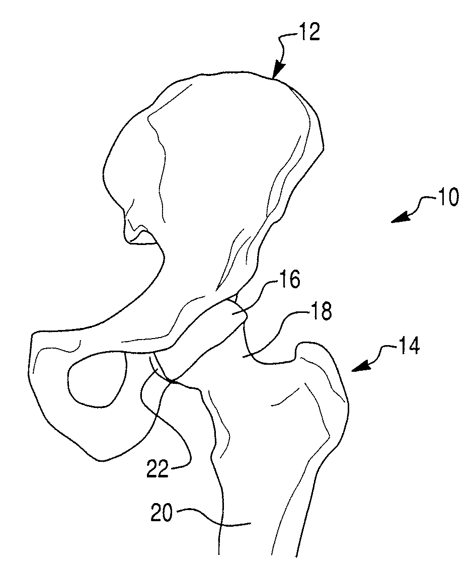
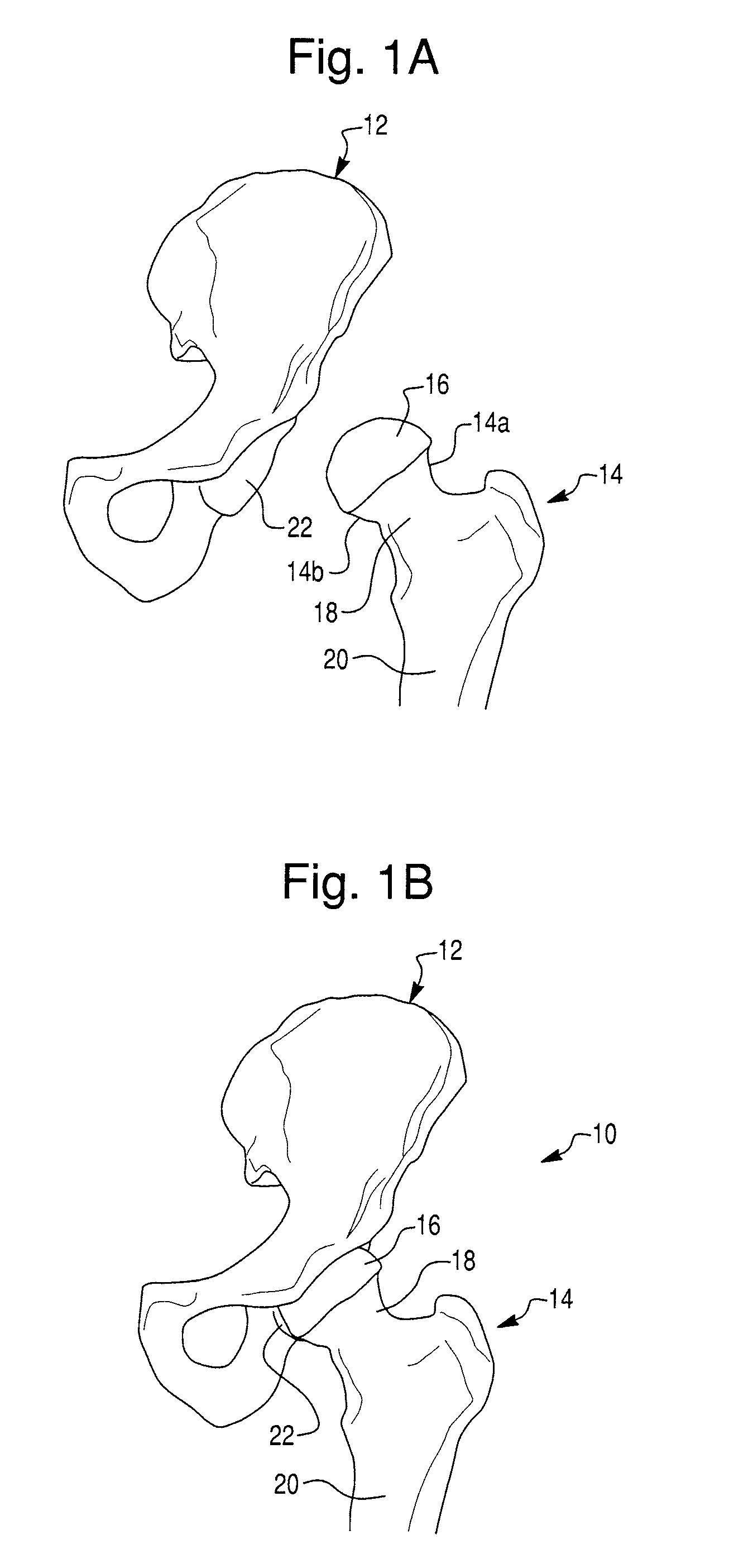
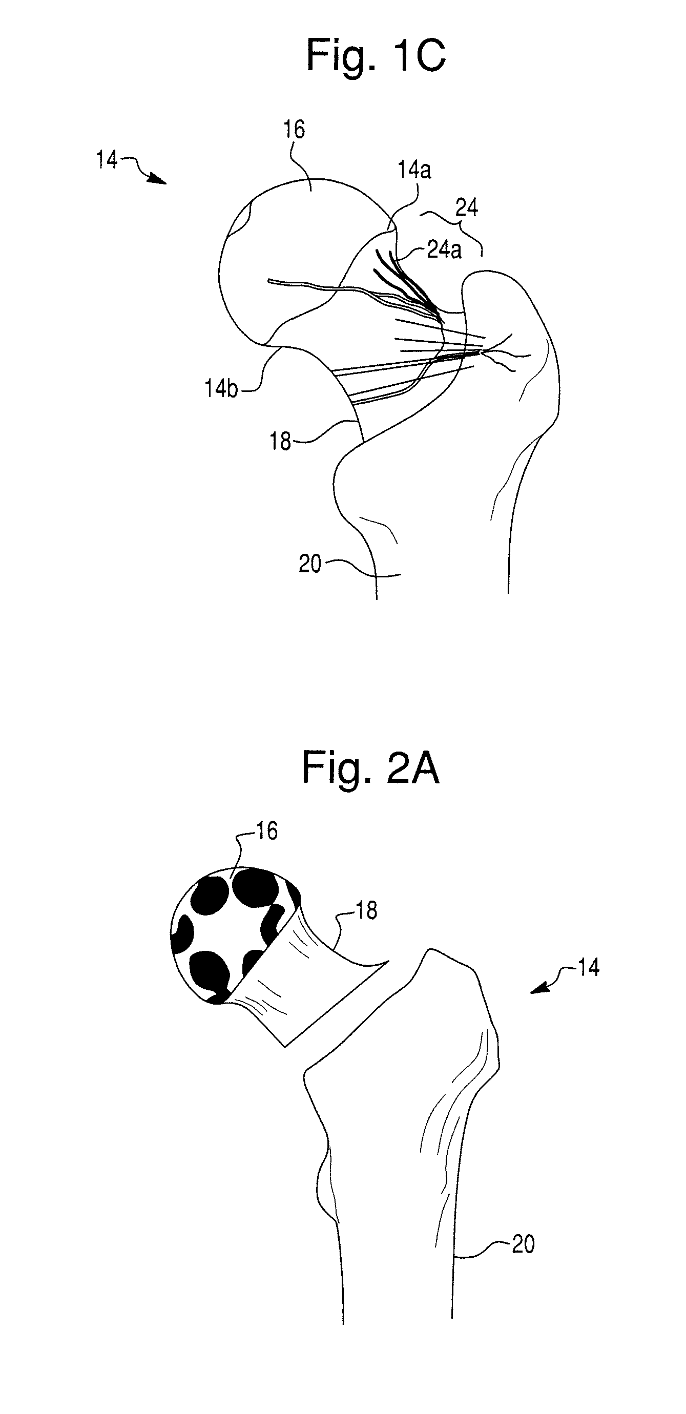
CROSS-REFERENCE TO RELATED APPLICATIONS[0001]The present application claims priority to U.S. Provisional Patent Application Ser. No. 61 / 007,033, filed Dec. 10, 2007, and U.S. Provisional Patent Application Ser. No. 61 / 005,990, filed Dec. 10, 2007, each of which is hereby incorporated by reference herein in its entirety.BACKGROUND OF THE INVENTION[0002]1. Field of the Invention[0003]The invention relates to orthopedic joint replacement and, more particularly, to a prosthetic device for use in orthopedic joint replacement and a system for preparing a bone to receive the prosthetic device.[0004]2. Description of Related Art[0005]FIG. 1A illustrates the bones of a hip joint 10, which include a portion of a pelvis 12 and a proximal end of a femur 14. The proximal end of the femur 14 has a superior aspect 14a and an inferior aspect 14b and includes a ball shaped part called the femoral head 16. The femoral head 16 is disposed on a femoral neck 18, which is connected to a femur shaft 20. A...

Claims


Application Information

Patent Timeline
IPC IPC(8): A61F2/32A61B19/00
CPCA61B17/1668A61F2310/00796A61B19/2203A61F2/30942A61F2/3603A61F2002/30125A61F2002/30769A61F2002/308A61F2002/30817A61F2002/30878A61F2002/30891A61F2002/3619A61F2002/4631A61F2230/0008A61F2310/00011A61F2310/00179A61B17/175A61B34/30A61F2002/30593
Inventor QUAID, ARTHUR E.
Owner MAKO SURGICAL CORP
Why Eureka
Try Eureka