
Insulation system and method for pre-engineered buildings

a technology for pre-engineered buildings and insulation systems, applied in heat-insulating buildings, industrial buildings, building repairs, etc., can solve the problems of reducing the heat insulation properties of blankets by a substantial amount, the thickness and corresponding rsi value of the wall insulation applied in blanket form has been functionally limited to 6 inches, and the weight of heavier insulation is difficult to manually support, so as to avoid compression effect of insulation

Active Publication Date: 2009-06-18
ARMAND HLDG
View PDF12 Cites 8 Cited by
  • Summary
  • Abstract
  • Description
  • Claims
  • Application Information

AI Technical Summary

Benefits of technology

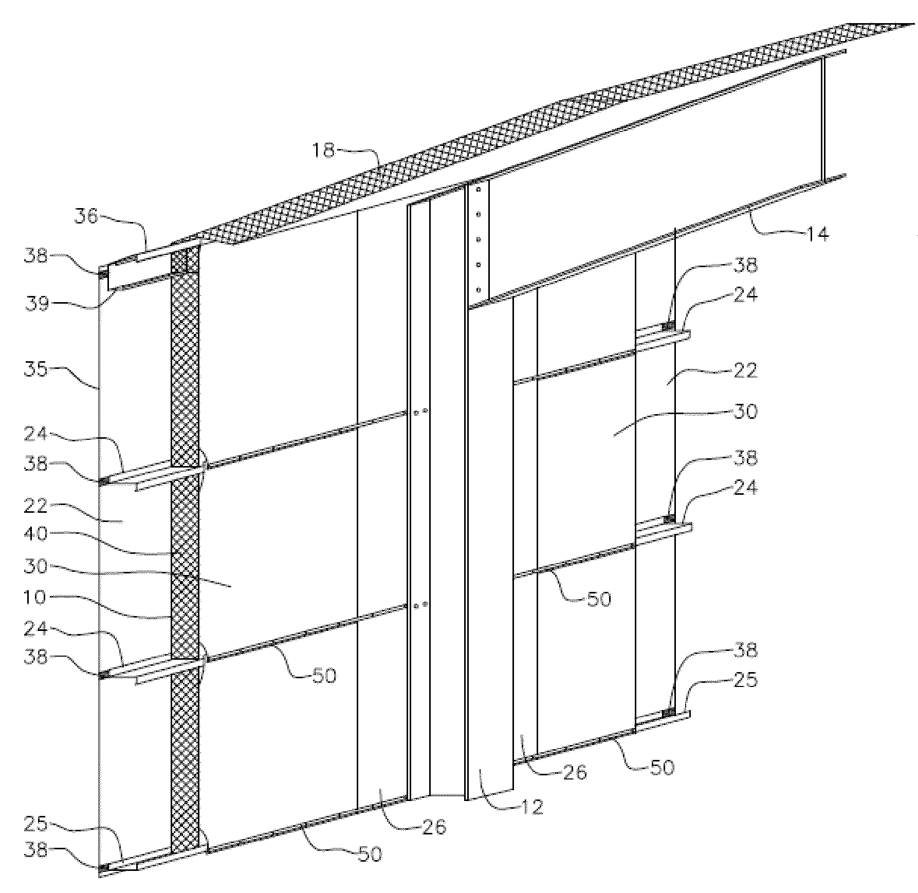
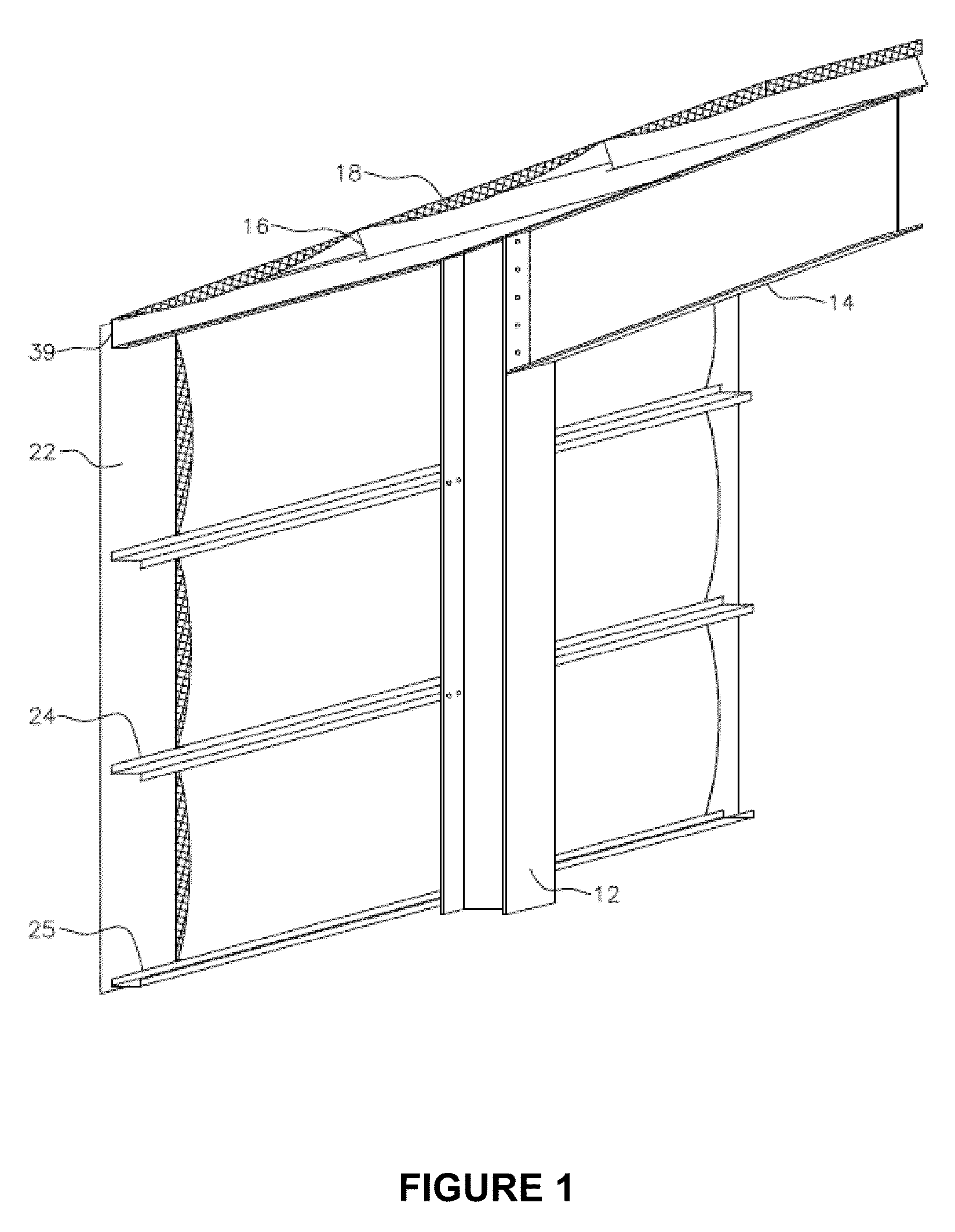
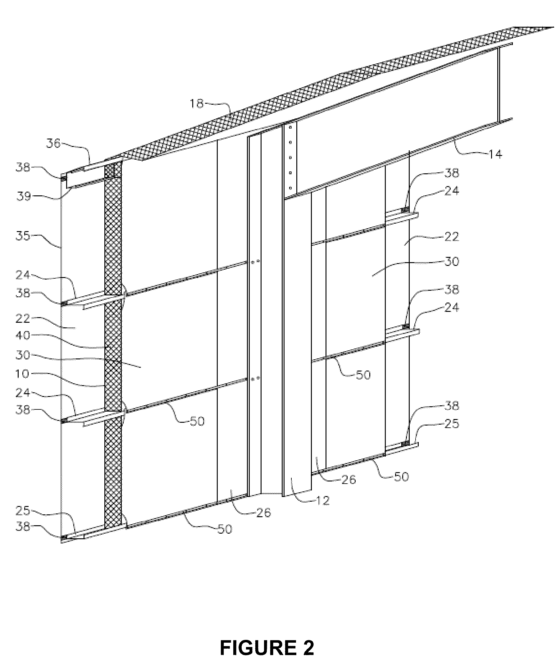
[0015]The invention provides a method of insulating a building framework for a by-pass wall girt metal building type. This building framework includes vertical structural wall columns, corner columns and roof structural members to support side walls, end walls and a roof, the wall and corner columns having exterior faces, the building framework further including parallel spaced horizontal wall girts connected to the exterior faces of the structural and corner columns, and parallel spaced roof purlins connected above and normal to the roof structural members. In the method of the invention, prior to connecting the wall girts, a vapor barrier extension member formed of vapor barrier material is connected to the exterior faces of the wall and corner columns. The vapor barrier extension member is formed with lap extensions which extend horizontally in both directions beyond the exterior face or faces of the wall and corner columns to connect to the interior facing of the later to be installed insulation. The wall girts are then connected to the exterior faces of the wall and corner columns, and insulation is installed between the wall girts. The insulation may be installed in one or more layers, with the innermost layer being formed with an interior facing, such as a layer of laminated vapor barrier. The lap extensions of the vapor barrier extensions are fastened to the interior facing of the insulation on either side of the wall and corner columns. This method allows insulation to fill the full depth of the wall girt cavity and avoids compression of the insulation when fastening the exterior cladding.
[0016]The method preferably includes installing the exterior cladding exterior to the wall girts, prior to the installing the insulation. This avoids the above-noted problems of installing insulation in poor weather conditions. The insulation is preferably a blanket of insulation material laminated to the interior facing, and the insulation is installed horizontally above and below the wall girts from the interior of the building. Insulation may be installed in multiple layers with a back layer of unfaced insulation material and the innermost layer being integrally faced / laminated vapor barrier blanket insulation.

Problems solved by technology

This compression substantially reduces the heat insulating properties of the blanket insulation along each attachment line.
However, the patent still relies on exterior installation of the blanket insulation, which has the problems mentioned below.
In the past, the maximum thickness and corresponding RSI value of the wall insulation applied in blanket form has been functionally limited to 6 inches due to a number of factors, including:a) the difficulty in compressing heavier insulations without significant deformation of the metal cladding; andb) the weight of heavier insulation becoming difficult to manually support.
The prior art insulation systems are additionally problematic when the insulation must be installed in poor weather conditions, particularly during windy or rainy conditions.
Since the insulation is installed prior to closing in the building with the exterior metal cladding, the insulation and workers are exposed to the environmental elements.
The blanket insulation can act similar to a sail catching wind, which causes the significant delays during erection.
During periods of significant rainfall the exposed insulation becomes saturated with moisture damaging the insulation and thermal effectiveness.
As well, the prior art building installation and insulation methods leave the horizontal wall girts exposed on the interior of the building space.

Method used


Image

  • Insulation system and method for pre-engineered buildings
  • Insulation system and method for pre-engineered buildings
  • Insulation system and method for pre-engineered buildings

Examples


Embodiment Construction

[0033]As used herein and in the claims, the word “comprising” is used in its non-limiting sense to mean that items following the word in the sentence are included and that items not specifically mentioned are not excluded. The use of the indefinite article “a” in the claims before an element means that one of the elements is specified, but does not specifically exclude others of the elements being present, unless the context clearly requires that there be one and only one of the elements.

[0034]As used herein and in the claims, the terms “side”, “end”, “vertical”, “horizontal”, “upper”, “lower”, “top” and “bottom”, and other like terms indicating relative positions above or below or to the side of a given point or element, are used in this description or figures to more clearly describe some embodiments of the invention. However, when applied to systems and methods for insulating pre-engineered buildings, such terms may refer to another relationship as appropriate. The term “exterior...


PUM


Abstract

A metal building insulation system and method for by-pass wall girt metal building systems which facilitates the installation of wall insulation applied from the interior of the building for the full depth of the wall girt. Integrally faced vapor barrier blanket insulation combined with vapor barrier extensions installed behind perimeter structural and corner columns before wall girt erection are preferred system components.

Description

CROSS-REFERENCE TO RELATED APPLICATION[0001]This application claims priority from U.S. Provisional Patent Application No. 61 / 014,333 filed Dec. 17, 2007, which is incorporated by reference herein to the extent that there is no inconsistency with the present disclosure.FIELD OF THE INVENTION[0002]This invention relates to systems, methods and components for insulating pre-engineered steel buildings.BACKGROUND OF THE INVENTION[0003]The construction of metal building systems, often referred to as “pre-engineered” metal buildings systems, includes building systems comprised of metal structural members (structural wall columns, corner columns and roof support members) with horizontal metal wall girts and metal roof purlins covered by integrally faced / laminated vapor barrier fiberglass blanket insulation and exterior metal cladding. The majority of these metal building systems incorporate what is commonly known as a by-pass wall girt design, in which the building support perimeter columns...

Claims


Application Information

Patent Timeline
IPC IPC(8): E04B1/74E04B1/76E04B1/78
CPCE04H5/10
Inventor STENSRUD, MICHAEL D.
Owner ARMAND HLDG
Learn More