Dehydrating device

a technology of a dehydrating device and a squeezing tool, which is applied in the direction of wringing machines, carpet cleaners, lighting and heating apparatus, etc., can solve the problems that the squeezing tool cannot be properly used, and achieve the effect of fast rotation, easy handling of the tappet unit, and fast rotation

Inactive Publication Date: 2009-06-18
DIKAI INT ENTERPRISE
View PDF4 Cites 34 Cited by
  • Summary
  • Abstract
  • Description
  • Claims
  • Application Information

AI Technical Summary

Benefits of technology

[0009]The advantages of the present invention are described as below. A user takes an aquiferous member as a rotational mop into the bearing member of the rotation unit. The rotation unit is driven to fast rotate by easily handling the tappet unit so as to drive the rotational mop very quickly. Continuousl

Problems solved by technology

Due to that the cloths distributed on the lower surface of the turntable are not long enough, the cloths are hardly to be combined as a fascination, so that the bucket having the squeezing tool

Method used


Image

  • Dehydrating device
  • Dehydrating device
  • Dehydrating device

Examples


Embodiment Construction

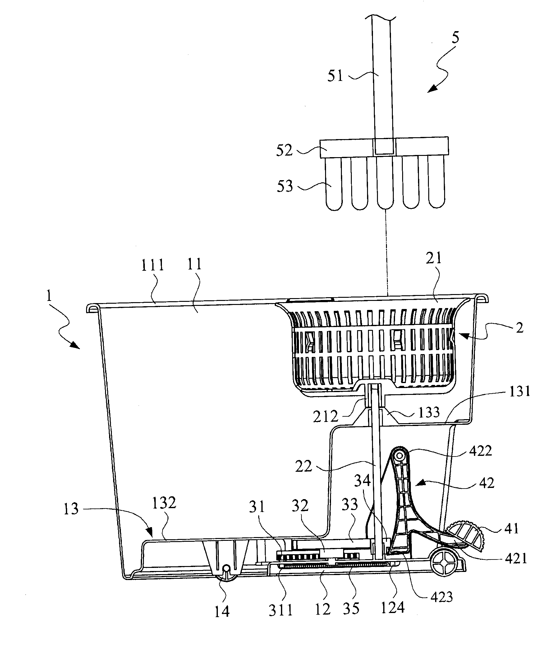
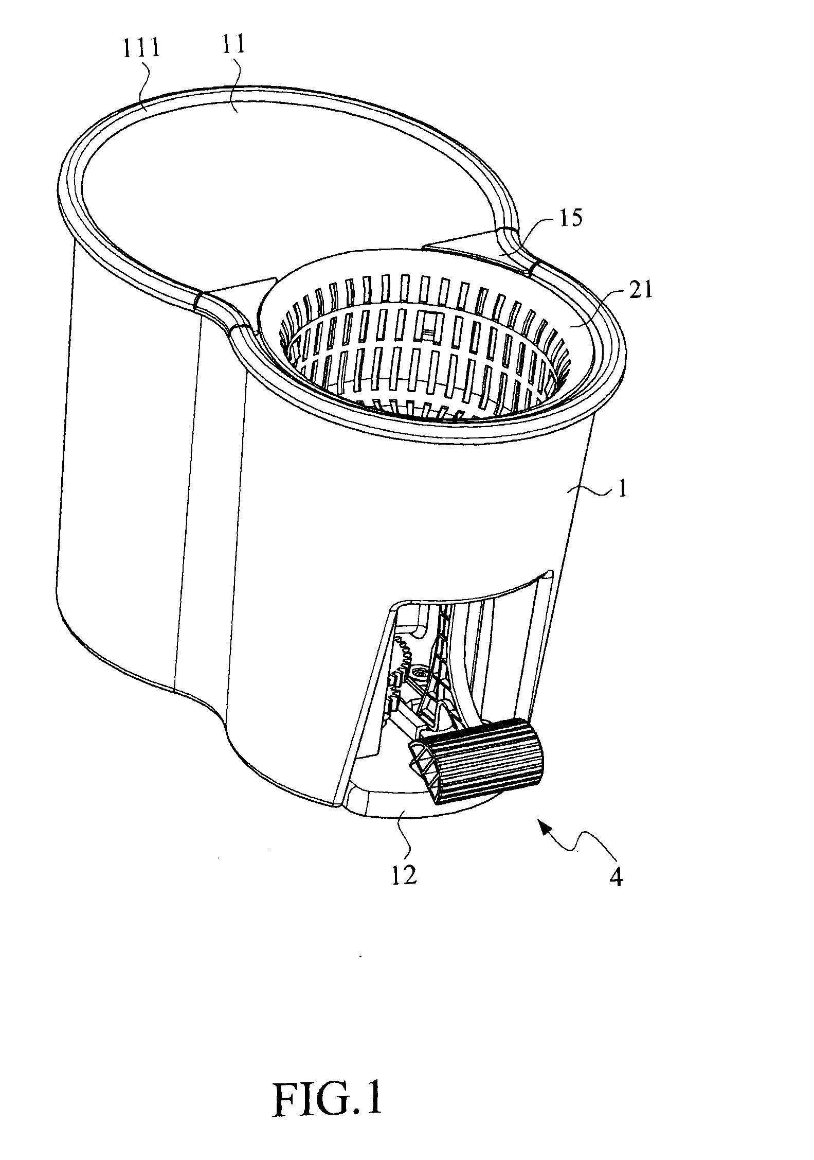
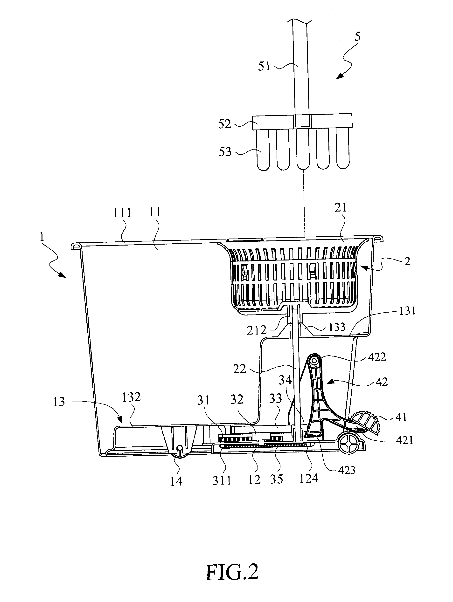
[0018]The present invention is a dehydrating device, which is able to dewater an aquiferous member 5. With reference to FIG. 1 to FIG. 4, the dehydrating device includes a body 1, a rotation unit 2, a transmission unit 3, and a tappet unit 4.

[0019]The body 1 is shape as a cylindrical structure, and the bottom of the body 1 has at least one roller 14 for the movement of the body 1. The body 1 has an accommodation 11 and an installation portion 12, a partition 13 is disposed between the accommodation 11 and the installation portion 12. The top of the accommodation 11 is an open 111 for the aquiferous member 5 and water entering into. The partition 13 is to avoid the leakage of the water in the accommodation 11 through the bottom of the body 1. The partition 13 has a higher portion 131 and a lower portion 132 in order to let the water flowing to the higher portion 131 be gathered up to the lower portion 132. The higher portion 131 of the partition 13 has a convex 133. The installation ...


PUM


Abstract

A dehydrating device comprises a tappet unit, a transmission unit and a rotation unit, wherein the rotation unit comprises a bearing member and a transmission shaft. A aquiferous member is disposed in the bearing member, and then the operation of the tappet unit is beginning. The tappet unit then mechanically drives the transmission unit and the rotation unit so as to dewater the aquiferous member.

Description

BACKGROUND OF THE INVENTION[0001]1. Field of the Invention[0002]The present invention generally relates to a dehydrating device, more particular to a device that comprises a tappet unit, a transmission unit and a rotation unit, and dewaters an aquiferous member while the tappet unit is operated to mechanically drive the transmission unit and the rotation unit.[0003]2. Description of the Prior Art[0004]Nowadays, mop is a major tool for cleaning floor. One of prior mops is consisted of a handle and some cloths connected to the one end of the handle. For dewatering on the purposes of fast and labor-saving, the most common use is to adopt a bucket having a squeezing tool to press the cloths for dewatering.[0005]Alternatively, another prior rotational mop is consisted of a handle, a turntable and some cloths. The one end of the handle is pivotally connected to the center of the turntable. The cloths are distributed on the lower surface of the turntable. While the mop is in operation, the...

Claims


Application Information

Patent Timeline
IPC IPC(8): D06F45/00
CPCA47L13/58
Inventor LIN, CHANG-I
Owner DIKAI INT ENTERPRISE
Why Eureka
Try Eureka