Method and arrangement for the energy-saving operation of dishwashers

a technology for energy-saving operation and dishwashers, applied in the direction of constant-current supply dc circuits, ac network voltage adjustment, applications, etc., can solve the problems of inefficient energy use, frequent finding of slow and cumbersome dishwashers of the described typ

Active Publication Date: 2009-06-18
MEIKO MASCHENBAU
View PDF10 Cites 29 Cited by
  • Summary
  • Abstract
  • Description
  • Claims
  • Application Information

AI Technical Summary

Problems solved by technology

The worst-case power demand is in this case that amount of power which is required for the rated power of the machine.
Dishwashers of the described type have numerous disadvantages which generally result from the operation of dishwashers such as these being very inefficient in terms of energy use.
These disadv...

Method used


Image

  • Method and arrangement for the energy-saving operation of dishwashers
  • Method and arrangement for the energy-saving operation of dishwashers
  • Method and arrangement for the energy-saving operation of dishwashers

Examples


Embodiment Construction

[0015]This object is achieved by the invention with the features of the independent claims. Advantageous developments are described in the dependent claims.

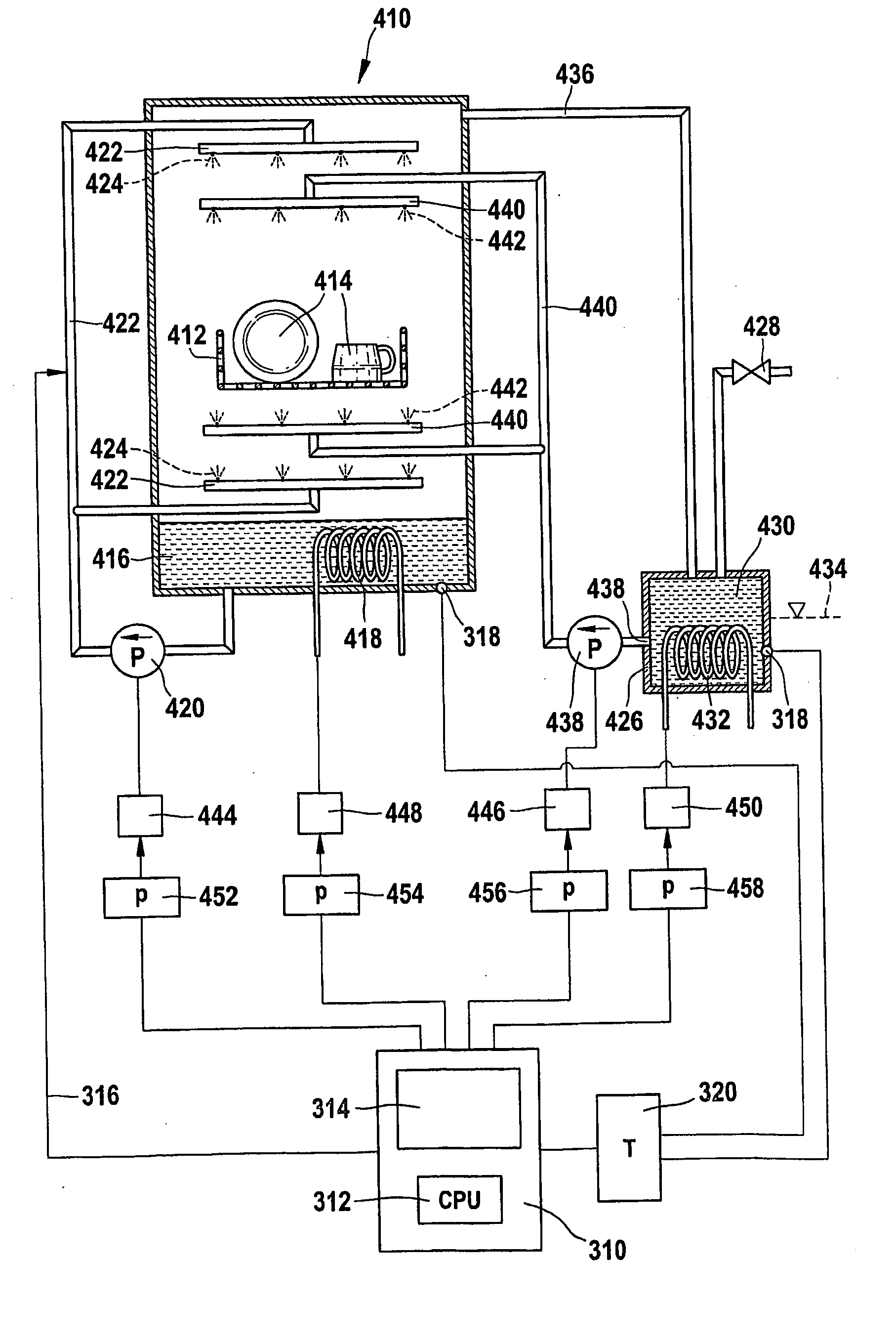
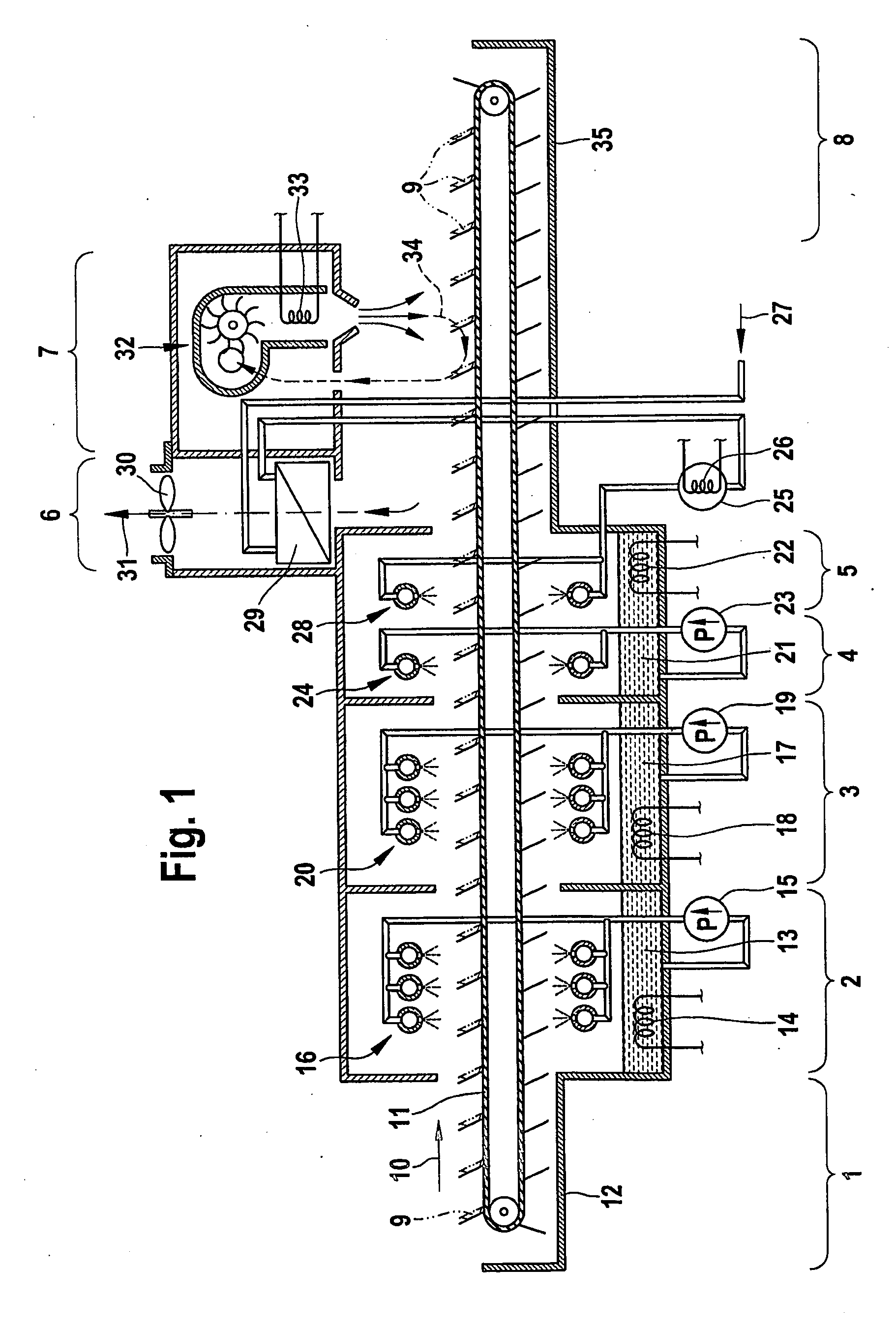
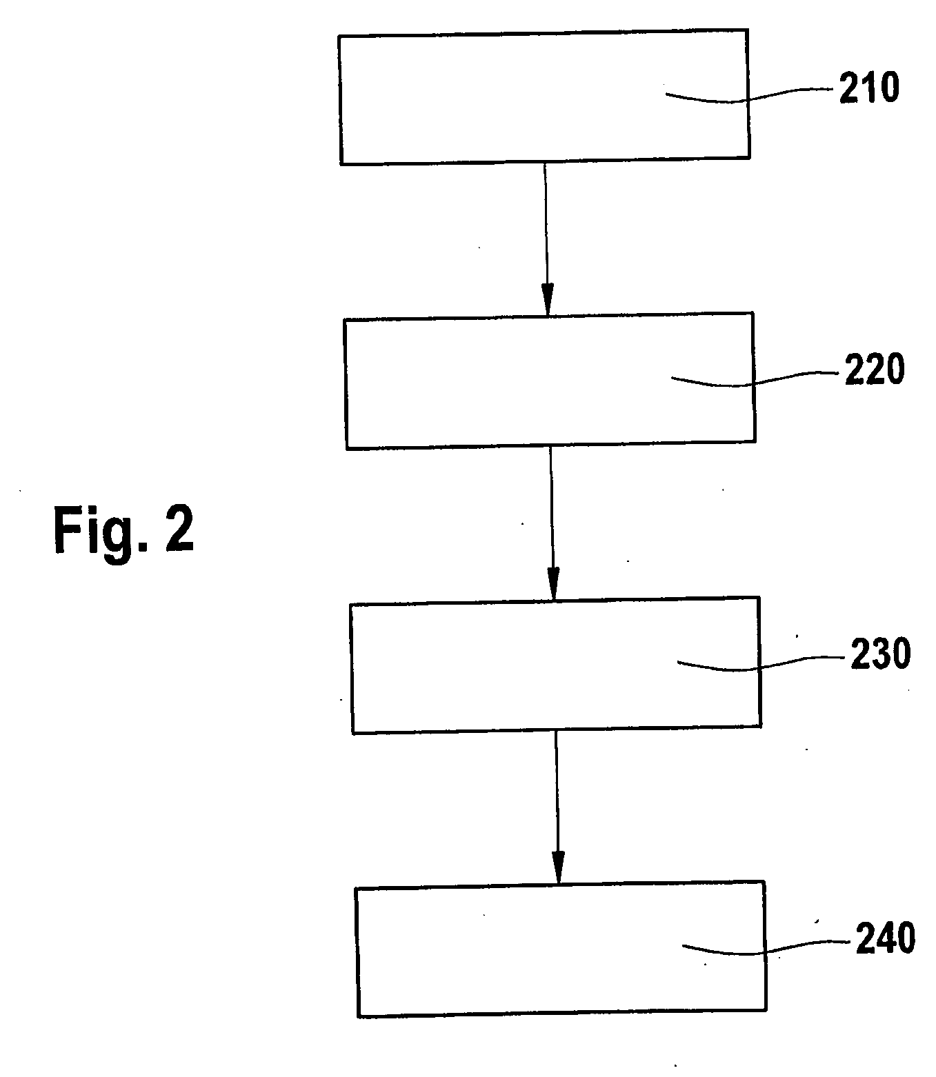
[0016]A method is proposed for energy-saving operation of a dishwasher, in particular for washing dishes or medical appliances, as well as an apparatus for in each case carrying out the method in one of the described refinements. The dishwasher may, in particular, be a multiple tank dishwasher. The method steps described in the following text need not necessarily be carried out in the described sequence. Further method steps, which are not included, may also be carried out. Reference is made to FIG. 2 for the numbering of the method steps.

[0017]The dishwasher should have a total number N≧2 of electrical load elements. As already described above, these load elements may, for example, be heating elements, pump elements, fans or drive elements. Further load elements may also be included, for example power supplies for controllers or...


PUM


Abstract

The energy-saving operation of dishwashers (110; 410) plays an important role, in particular for larger enterprises, e.g. for the canteens of hospitals or large enterprises, and in the medical disinfection field. The invention thus discloses a method and a device, in which a total maximum electric output is assigned to a group of electric consumer elements (14, 15, 18, 19, 22, 23, 26, 33; 418, 420, 432, 438) of a dishwasher (110; 410). In addition, at least two output levels are assigned to each electric consumer element (14, 15, 18, 19, 22, 23, 26, 33; 418, 420, 432, 438) of said group. An optimum combination of output levels is then selected in a requirement determination step, based on an operational state B of the dishwasher (119), whereby for each consumer element (14, 15, 18, 19, 22, 23, 26, 33; 418, 420, 432, 438) the selected output level is adapted to the output requirement of the consumer element (14, 15, 18, 19, 22, 23, 26, 33; 418, 420, 432, 438) in operational state B and the total output of all consumer elements (14, 15, 18, 19, 22, 23, 26, 33; 418, 420, 432, 438) does not exceed the maximum electric total output. The operation of the dishwasher (110; 410) can also be divided into three phases, a start phase, an activation phase and a load control phase. The output levels of the individual consumer elements (14, 15, 18, 19, 22, 23, 26, 33; 418, 420, 432, 438) are optimally adapted in accordance with the requirements in said operating phases, thus allowing a response to be made to any fluctuations in the operational state. The inventive method permits significant energy savings to be made in comparison to conventional methods for controlling dishwashers (110; 410) and leads to a more rapid attainment of a ready status of the dishwasher (110; 410) upon activation.

Description

FIELD OF THE INVENTION[0001]The invention relates to a method and an arrangement by means of which dishwashers can be operated with more energy being saved. One particular aim of the invention is to allow energy-saving operation of multiple tank dishwashers with washing zones, a rinsing zone and a drying zone.PRIOR ART[0002]Known machines, such as the dishwashing and drying installation described in DE 44 36 359 C2, typically have heaters installed for the individual loads, that is to say for the individual zones. These heaters are sufficient to cover the respective worst-case power demand. The worst-case power demand is in this case that amount of power which is required for the rated power of the machine.[0003]The heating power levels in the individual zones differ, depending on the method being used. The installed heating power levels are in each case switched on and off depending on the instantaneous power demand. The addition of the heating power levels which are required for t...

Claims


Application Information

Patent Timeline
IPC IPC(8): A47L15/46
CPCA47L15/0047A47L15/0078A47L2501/06A47L15/247A47L2401/12A47L15/245
Inventor ECKER, ENGELBERTEGGS, MARCUSZAPF, DIETMARSTREB, MICHAEL
Owner MEIKO MASCHENBAU
Why Eureka
Try Eureka